Technical Break down of smurf !

Currently reading:
Technical Break down of smurf !

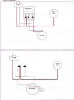
Darryl...the voltage regulator/cutout box is just an ornament if you have an alternator. It could be removed but people tend to use it for connecting cables. The internal workings should be inoperative as the alternator's little attachment on the side does what it did with the original dynamo. So those instructions are not relevant to your car.
Can you locate the "continuity" setting on your meter. It is the one where it beeps when you join the red and black ends. We can find thing out safely with that setting.
 
HI Darryl,

that picture you posted is the Control Box normally associated with a Dynamo. It is not a pure regulator as it carries out 3 functions for the Dynamo
Voltage Regulator - keeps output down to 14.2V (as per the pure Alternator Voltage Regulator)
Voltage Cut Out - set to 13.2V - when the car is idling the output of the dynamo could fall below this so the battery will try to drive the dynamo. The Voltage cut out prevents this. An Alternator has a rectifier (Diode) pack in the output so it cannot get reverse currents flowing
Current Regulator - dynamos cant handle high charging currents so these trip out at a preset current. Alternators do not have brushes in the output field so can handle much higher currents.
The Voltage Regulator on your alternator is that little finned box with the green and yellow wires mounted on the side of the alternator.
When the car had an alternator conversion the wiring should have been altered to suit and the Dynamo Control Box recovered. Control Boxes when they are used must have a cover as they are calibrated and adjusted with the cover on.
On first inspection it looks as though the wiring has not been altered but you need someone on the forum who has an Alternator conversion to confirm this.
I've attached a VERY basic diagram to show the before and after of what the conversion should look like. The colours may vary according to the model.
Hope I haven't muddied the waters
Richard
 

Attachments

  • Dynamo to Alternator conversion.pdf
    315.9 KB · Views: 76
Yes, just googled the continuity setting. So I should be able to chase some of the wiring down. I will deprecate and clean contacts.
I know
- cable from stater

I presume I need to find
- B+ brown from generator ( probably brown wire to left )
- black from the generator for dash light ( black wire on left or middle )

That leaves
- red on the right ?
- 1 black cable - left or middle ?

Any idea what the wiring should be ?

I have found info that this is correct :
1 post -red from dash
B+ from alternator
Black from starter motor
2 post - black (red) from dash
Black generator dash light

Not 100% if this is correct !
Darryl


-
 
Hi
Didn't get anything done today, man flu !
Hope to chase cables tomorrow but pretty sure they have not been moved from the change to alternator.
Do you know how to check the old regulator is not working ?
 
Hi Daryll it's definitely still wired in circuit and working, as it is still wired for a Dynamo setup. Which explains why you are getting odd voltages. Those connectors on the regulator that the wires are bolted to actually run up the back of the unit and connect to the relays inside.

You need to wire it as the diagram below, so it maybe worthwhile taking the VR off and gutting the thing, removing all the relays etc and just using it as a junction box, so not only making use of it still but it maintains a bit of originality.

Whoever drew this diagram for some reason didn't draw it as the connections appear on the actual VR. From left to right it should be 51 67 30. What I mean is the wires are connected to the correct terminals numbers in the diagram but it doesn't actually represent the layout on the VR correctly. If that makes sense.:confused:

Tony
 

Attachments

  • IMG_6328.JPG
    IMG_6328.JPG
    126.8 KB · Views: 37
As I understand it, if the control box is handling connections from your alternator, the only terminals that will ever be live are the one from the B+ (always live) and one that may be connecting from the alternator's attached regulator to the cable that goes to the charging light. Any other cables are either superfluous ones from the old dynamo or serving some other purpose.
So there is really no functionality to test and the thig is a red herring. You could achieve the same by using good quality connectors. it just happens that the terminals of the box are perfect for the job.
....just noted from Tony's post as the terminals do connect internally via relays, there may be some funny business going on inside it as I suspected!!! So that might explain your permananent ignition light.
Can you just reduce the connections to the basics with carefully insulated connector blocks just to verify it all works for now?
 
Last edited:
As I understand it, if the control box is handling connections from your alternator, the only terminals that will ever be live are the one from the B+ (always live) and one that may be connecting from the alternator's attached regulator to the cable that goes to the charging light. Any other cables are either superfluous ones from the old dynamo or serving some other purpose.
So there is really no functionality to test and the thig is a red herring. You could achieve the same by using good quality connectors. it just happens that the terminals of the box are perfect for the job.
....just noted from Tony's post as the terminals do connect internally via relays, there may be some funny business going on inside it as I suspected!!! So that might explain your permananent ignition light.
Can you just reduce the connections to the basics with carefully insulated connector blocks just to verify it all works for now?

Probably a good idea before gutting the VR if that is the way you want to go. Just make sure the connector that connects all the +'s together, battery, starter and ignition wire together is chunky enough, i.e. Rated high enough to handle the battery current.
 
Hi Darryl,

as per comments above I think you have some kind of halfway house wired up. The Dynamo Control Box (DCB) is best taken out of the equation.
To work out which wire is which I would suggest the following:-
1 - Identify cable from Battery - with the ignition switched off set the meter to 20V range, measure the voltage at the battery. Now with the meter negative on a good earth (alternator body?) measure the voltage at the DCB terminals. One of those fat cables should give exactly the same reading - this is the battery feed. Since the DCB is still in circuit you may get some strange readings at other terminals - ignore these

2 - Identify Alternator B+ cable - disconnect the negative at the battery post to isolate it. Put your meter to 200 ohms resistance range. Connect meter negative lead to the alternator B+ post. Measure the resistance of one of the other thick cables and one should give you a near zero reading - this is the Alternator charging cable (B+).

3 Identify Ignition Warning Light (IWL) wire. Reconnect Battery negative clamp. Turn on ignition. With the meter set to 20V range measure the voltage of the thin wires at the DCB - this should be near 12V.

Now switch off and disconnect the negative battery post again to isolate the 12V supply.

These are the three cables you need for an alternator set up.

The battery feed needs to be connected to the Alternator B+ cable. If you use a connector block make sure it's beefy enough. A 30 amp mains block should do as the alternator usually will throw out 16A max at full charge.
Make sure this is well insulated, can't flap about and is not near a heat source
The IWL wire needs to be connected directly to the IWL terminal on the alternator.
The other wires on the DCB are the old DF and D+ wires which are now spare and can be taped out of the way.
Before connecting the battery back up, set he meter to 200 ohms range and measure the resistance between the battery feed cable and earth (remember to keep the negative post of the battery disconnected!).
If you get any low reading do not reconnect the battery negative as there is a short to earth somewhere which must be sorted before reconnecting the battery.
If you're happy with the wiring reconnect the battery post. If you're at all nervous, get a 5A mains fuse, hold it against the negative battery clamp and then touch the other end of the fuse against the battery negative post. If there's a short the fuse will blow before any damage is caused.
If it reads OK (or the fuse doesn't blow) then reconnect the negative battery post and fire up and test for charging.
Hope the above helps
Richard
 
Hi all
I have chased wires in regulator with a mix of continuity / what I can see / guesswork.
What I have found
51
Black to B+ on generator
Iwl to dash ( guesswork and it is green )

67
Iwl to generator

30
Red to fuse ( guesswork and it is red )
Black to starter

Earth cable on bolt holding junction box on ( guesswork )

I have removed the regulator and taken all the gubbins out, photo attached. Tested for continuity and all seems good to use as junction box.

I will wire up as
51
Iwl to generator
Iwl to dash
67
Earth that was on bolt holding regulator on
30 red to fuses
Black to starter
Black to B+ on generator

My question is ? ( more, I know ! )

The regulator is a Marelli and stamped 12v and 16amp, is this safe ?

30amp was mentioned previously!

Thanks all again
DarrylIMG_1478357900.664305.jpg
 
Hi Darryl it will be fine. You are only using the three metal tabs to join the wires together, they will be more than able to handle the current. The internals are the bits rated at 16 amps.

Tony
 
It is perfectly safe for current in question
The load indicated is for the now removed internal components
 
Found this online, marelli coil with ballast attached IMG_1478363706.516026.jpg
 
Hi,
Off the radar for a few days !
Got out for a few minutes to clean up connectors and crimp on a new ring connector for just one cable.
Unfortunately there isn't the space to get all 3 rings on to one connector so have stripped out all the innerds of the old regulator and reattached as the middle and right are joined.
So I will put one cable in the centre and two to the right and should have no connection issues. It also leaves the left post for the other two cables.
I have attached a photo.
Does anyone think this is a bad idea !
Too dark now to get out and test so will finish tomorrow and hopefully put this all to bed.
Darryl
IMG_1478969405.813158.jpgIMG_1478969423.543984.jpg
 
I actually went one further and took those spindles out so all as I was left with was the back plate with the 3 connectors
 
I had all the spindles out but could not get the three cables on one connector !
 
All connected and checked with fuse prior to connecting negative post of battery. Started perfectly and took for a spin, all seems well , generate light comes on at starting and goes off after a few moments or a little rev.
I just have to check if the alternator is charging the battery. Is it a case of reading the voltage at the battery while revving the engine ?
 
Back
Top