Technical 2007 Ducato 2.2 100 Multijet - Fuel Gauge Problem

Currently reading:
Technical 2007 Ducato 2.2 100 Multijet - Fuel Gauge Problem

Elmo1954

New member
Joined
Apr 8, 2022
Messages
11
Points
2
Location
North East - Stockton
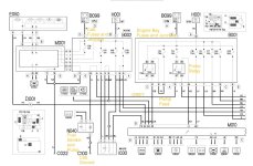
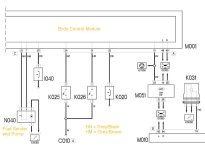
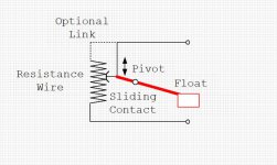
I am a newbie to the Forum. I have a FIAT Ducato, 2007, with 2.2 Diesel Installed. I got this with quite a few electrical problems, I have found available wiring diagrams difficult to obtain, those I have found are often unreadable. I have now fixed all problems (Rear Lights, Wipers, Heater Blower, and Horn) except 1, the Fuel Gauge. I have the connector that has 4 wires, a thick Grey one, a thick purple/black, a thin Grey/Brown (or dark Red), and a thin Grey/Black. The only drawing I can find shows that PIN 4 (thick Grey) should be Motor Pump Power Supply, and on testing. this wire is live with the Ignition on. My small drawing also states that PIN 1 (thin Grey/Brown) is Fuel Level Sensor Power Supply, however, this wire is NOT live with the Ignition on... Q: should it be? The thick Purple/Black, and the thin Grey/Black are Ground wires respectively.
Simple Fuel Pump Wiring.jpg


With no diagram that simply says 'this wire should be live and comes via 'X' fuse or wherever', I am at a loss... in my much younger days you took off the unit's connector and put it to earth, if the gauge moved, the sensor/resistor was gone, that was easy lol.

I would be really appreciative of any advice, especially if someone can point me to an 'idiots guide' wiring diagram, or a link. I have tried looking in the Workshop Manual and the Trainers Guide Part 1 for the diagrams but no luck there, searching the Peugeot and Citroen diagrams seem equally as illusive?
Many thanks in anticipation...
Paul
 
Hi Paul

I attach some diagrams based on both eLearn and the Training manual. As the training manual was issued fairly early in the vehicle life, it contains a number of errors and the pin numbering for the 4 pin connector on the Fuel Pump/Sender assembly is back to front. However, your interpretation of the wire functions is correct, i.e.:

Thick Grey - Fuel Pump Live
Thick Black/Violet - Fuel Pump Ground
Thin Grey/Brown - Sender Positive
Thin Grey/Black - Sender Negative

Note that both wires for the sender go back to the Body Control Module. I would expect the Sender Negative to be near ground potential (It goes direct to the BCM to avoid small ground voltage differences from upsetting the reading). I would expect there to be some positive voltage on the Sender Positive (depending on the level of fuel and its resistance) but it doubt it gets higher than about 3 volts.

The BCM monitors the resistance, calculates the fuel level and sends that information digitally via CanBus to the instrument panel. Here it is converted to a drive for the fuel gauge needle (stepper motor type) and low fuel warning lamp.

I guess the first thing to check is the two wires from Fuel Sender to BCM, and the resistance of the Sender which should vary from 300 ohms empty to 20 ohms full.

The Canbus is not really checkable without specialised equipment, and if it failed you would lose more than just the fuel gauge.

The final possibility if the gauge needle is frozen (e.g. reads zero all the time) is that it has become mechanically stuck through lack of use. Some folks have had success by judicious tapping of the cluster, others have dismantled it and "exercised" the pointer a few times. This is what "Ducatiman" had to say a while ago:

"Just stripped out the instrument panel, gave all four analogue gauge needles a good working backwards and forwards and hey presto! All working again!!

I wonder just how many people have been ripped off for a new ECU when they have had this issue??
Simple to access, just 4 screws to take out using a 25 size Torx driver, the first two aren't that obvious, one up under the upper corner of each side of the panel cover.
Once they are removed lift the grey panel from the back (2 spring clips there so you need to pull on it a bit)
That leaves the instrument cluster held in by 2 more screws at the rear of the panel vertically positioned into the mounting plate. Take those out then disconnect the multi way connector.
You now need to carefully pry apart the snap fittings around the edge of the instrument cover the when the covers are in two pieces lift out the centre piece.
The needles are now accessible so gently give them a wiggle through the normal operating range, leaving them roughly where they should be with ignition switched off.
Plug it back in and give it a try before putting it all back together in reverse order to the dismantling process."
 

Attachments

  • X250 Fuel Pump.jpg
    X250 Fuel Pump.jpg
    170.3 KB · Views: 338
  • X250 Fuel Sender Resistance.jpg
    X250 Fuel Sender Resistance.jpg
    76.6 KB · Views: 249
  • X250 Fuel Sender.jpg
    X250 Fuel Sender.jpg
    81.2 KB · Views: 405
Hi Anthony489, thanks for coming back so quickly, and with a detailed explanation and 'plan' of where to start. I believe the fuel pump.jpg you sent will be most useful, as your diagram includes 'proper' names for what each component is. I have been finding that component ID's, as well as variations with wiring colour codes, have been the most challenging. I did manage to decipher the other issues I had originally (after my wife pointed out that Black = N for Noir, and White = B for Blanc... talk about feeling stupid).

A few things I noticed after posting originally: 1) When the sender connector is unplugged and the Ignition is on, the Orange light on the Fuel gauge flashes, it shows a continuous Orange light when connected? 2) When I switch the Ignition on, there is a minute movement of the Fuel Gauge needle, it returns back down after switching off, this is an extremely small movement though, not sure if this is significant? 3) The thick Grey wire to the Fuel Pump is live with Ignition on, but the voltage stops after a period, voltage resumes again if I switch Ignition off, and back on?

Just so I have understood your explanation correctly, as I would like to make aboslutely certain before I dive in!
1. The small voltage (around 3v) you mentioned, I assume this small voltage is from the BCM into the Fuel Sender Unit via the Grey/Brown wire? If not, where does that small voltage come from?​
2. This is returned to the BCM via Grey/Black wire, with a resistance to ground, depending on the fuel level?​
3. The BCM then interprets that signal to the Fuel Gauge?​
As said, I apologise if that's a stupid question, I know little about modern vehicle wiring, gone are the days when a positive and ground to a bulb made it light up!

I will follow your advice and start by checking continuity between Fuel Sender and BCM, then check for any voltage on the Grey/Brown wire, and come back with what I find. Please shout out if I have things wrong.

Once again, so many thanks
Paul
 
Hi again Paul

The wiring colour letters are based on Italian, here is a list:

A (Azzuro) = Light Blue
B (Blanco) = White
C = Orange
G (Giallo) = Yellow
H = Grey
L = Dark Blue
M (Marrone) = Brown
N (Nero) = Black
R (Rosso) = Red
S = Pink
V (Verde) = Green
Z = Violet

The supply to the fuel pump is controlled by the ECU via a relay. It comes on briefly when you first turn the key, then (from memory) turns off until the engine has started and then comes back on again.

The blinking fuel light indicates a fault, by unplugging the sender the circuit's built in diagnostics detect a resistance higher than the expected range (= open circuit ). The steady light indicates a resistance between about 280 and 300 ohms, corresponding to 10 to 0 litres reserve in the tank. This is good news, since it indicates a functioning path through from sender to instrument cluster.

I have attached a diagram showing a representative fuel gauge. Don't take the figures or the arrangement as set in stone, this is just something I drew to give you an idea of the most likely way Fiat have done things. The BCM has a stable +5 volt supply which is fed via a fixed resistor to the tank sender. The sender earthy end is returned to the BCM via a second wire. The voltage across the sender, which varies with fuel level/resistance, is monitored by the BCM and turned into digital data to be sent to the cluster.

It's possible that your sender is mechanically jammed at the empty end, so is stuck at 300 ohms regardless of the amount of fuel in the tank. You can test this by unplugging the harness and measuring its resistance with an ohmmeter. I assume you really do have more than 10 litres in the tank ! If it is stuck, the next step is to remove the pump/sender from the top of the tank (messy !) and investigate/replace.

You can test the rest of the level measuring setup by connecting a substitute resistance to the harness plug, in place of the sender. A resistance of about 150 ohms would be a good choice, as it ought to give a reading of around half full. If you don't have access to electronic components, the coil of an automotive type relay has typically 70 ohms resistance, so you could use a spare relay coil just as a resistor. The 70 ohms value should give a reading of about 3/4 full.
 

Attachments

  • Representative Fuel Gauge.jpg
    Representative Fuel Gauge.jpg
    270.9 KB · Views: 121
Anthony, your knowledge and assistance here is absolutely invaluable. Both your explanations have helped me understand how this works, and your last drawing pictures exactly how I thought it must be.
I also have an old 1998 V8 Jaguar project, and have quite a few spare relays, plus those I got when doing the earlier problems on the Fiat, though the heater problem turned out to be a resistor unit inside the blower motor.

I think it best to pull the Sender Unit, plug it in, and manually move the float and see what it tells me... yes? It doesn't look easy to get out mind!

Once again, I can't thank you enough.. I will report back.. looks like the weekend is booked!
Paul
 
Hi

Thanks for the measurements.

They suggest that the circuit arrangement is a little different to the one I suggested, but this doesn't matter. The main thing is that you are getting a voltage supply from the BCM and you have no wiring open or short circuits.

Your resistance measurement is interesting. Because an ohmmeter introduces its own little voltage/current into the circuit being tested (in order to carry out the measurement) it should only be used with the circuit powered off. If the circuit is still powered, the ohmmeter will affect circuit operation and vice-versa, so you won't get a sensible measurement. Hence the "open circuit" reading of 1--- or somesuch. To read the sender resistance you need to pull off the harness connector and probe straight onto the sender.

The good news is that applying the ohmmeter probes has inadvertently affected the reading on the fuel gauge, which suggests that everything except the sender is working.

To me this leaves two possibilities, either the float is mechanically stuck, or the float can move but the sliding contact isn't touching the resistance element. You may still get a 300 ohm fixed reading because optionally the top end of the resistance track is electrically connected to the slider - see picture.
 

Attachments

  • Tank Sender Principle.jpg
    Tank Sender Principle.jpg
    198.9 KB · Views: 54
Thank you again Anthony. I am working on the van over the weekend, though I may be able to do the resistance test before then and let you know. I am of the increasing opinion the float is stuck, or not contacting as it should, so I beieve the Sender Unit will need to be removed. From what I can see, that could be problematic in itself! If the Sender Unit needs to be disconnected to do the resistance test (which makes perfect sense following your explanation) then it may well be worth the effort to get it out and do the test on the bench?
Paul
 
Hello Anthony, many apologies for my late reply, you wouldn't know, but I am a disabled person and sometimes cannot get out to work as often as I would like.
I did the resistance measurement yesterday evening, and as you suspected the resistance 299 ohms.
I contacted the previous owner who told me that someone who had the van on a lift had told him that the fuel tank had been 'dented'? I thought they were a plastic tank, but, if it has been dented then that could have jammed the float. Either way, you're analysis of this looks to be spot on, fuel sender out and check.. but it looks a bit awkward to get out and there's a sepcial tool required :unsure:, unless there's a neat trick?
Paul
 
Hi again Anthony. Well, I found the problem, however I have absolutely no idea how this can have happened? In picture below is exactly as it came out of the tank. The float, bent rod (or pickup pipe?), piece of white plastic, and some used up electician's tape. (Ignore the hub and driveshafts, just took them out of powder caoting).

The unit itself has another rod bent to the left as you look at it, broken case, and pieces that go wherever!. How could this have happened?
20220704_174839.jpg


20220704_174905.jpg

I did put my arm down into the tank to retrieve the float from the bottom, along with the plastic, red tape, the long spring, and the pickup pipe.. there didn't appear to be anything that would obstruct the unit (no dents or lumps). I'm at a loss, though it's evident I need a new one!
Paul
 
Hi again Anthony. Well, I found the problem, however I have absolutely no idea how this can have happened? In picture below is exactly as it came out of the tank. The float, bent rod (or pickup pipe?), piece of white plastic, and some used up electician's tape. (Ignore the hub and driveshafts, just took them out of powder caoting).

The unit itself has another rod bent to the left as you look at it, broken case, and pieces that go wherever!. How could this have happened?
View attachment 408783

View attachment 408784
I did put my arm down into the tank to retrieve the float from the bottom, along with the plastic, red tape, the long spring, and the pickup pipe.. there didn't appear to be anything that would obstruct the unit (no dents or lumps). I'm at a loss, though it's evident I need a new one!
Paul
Hi Paul. I am away in my camper at the moment and don't have all my notes. However I can hazard a guess at what happened. Some numpty has tried jacking up the van under the plastic tank. The tank will have been squashed in until they realised what they were doing. This will have damaged the sender. Once they removed the jack the plastic tank will have popped back into shape leaving the damaged sender behind. You might be able to repair it, but any adhesive or stick tape is a non starter as it will be dissolved by the fuel. Remember that you are supposed to use a new large O ring each time it is disturbed. Good luck !
 
Thanks for your reply Anthony while you are away, I hope you're enjoying a break?
Yes, having looked under the van your diagnosis appears to be the right. There are marks on the bottom that would indicate a jack or similar, to snap and bend those upright bars it must have been some force.. such as the weight of the van!
I received a new unit today, and have been trying to fit it, but it appears I made a boo boo! I never replaced the screw-down ring when I took it off, now it won't go back on., no matter how I try. I am assuming the unit stands proud of the top of the tank, then you push it down into the tank and secure the screw-down ring.. am I correct? Now I need to source a new seal and screw-down ring that isn't distorted.. what a palaver!
Paul
 
Please let me know when you have returned, I am having a really 'bad hair day' refitting this new unit lol. I got a new screw-down ring and new seal, but the new ring will not go on either?

I am making a tool to put this on with, hopefully that will help me push down the Sender Unit and the ring to secure it all in place, I just hope I'm doing this right.
BTW: I connected the new Sender and manually moved the float, worked a treat.
Paul
 
Hi Paul. I am still going to be away for another week, but to be honest I can't add anything more to the procedure in elearn. I understand that Fiat dealers use a special tool, and there are universal types sold online or you can make your own I guess the idea is that you can push down and turn at the same time, which is hard to do with just hand pressure. I am not aware of any design changes over the years that would cause fitment problems, but I guess it's always possible.
 
I understand Anthony, your help has been absolutely invaluable, I would not have got this far without your help and knowledge.

On closer inspection, it looks to me like the force of jacking it up not only smashed the sender, but also distorted the tank neck.

Thanks again Anthony, I should get it sorted from here.
Paul
 
Back
Top