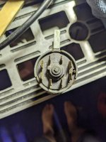
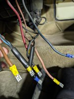
Hopefully a Forum Member will have more specific knowledge.
However in general terms using a voltmeter how many live wires do you have? I am assuming the thick brown is the main battery feed to the ignition switch (pin30/1) a (pin30) should also be live and gives constant power to some fuses irrespective of switch position, Int seems to be to headlight switch and the thinner red possibly the starter wire(pin50)? . (15/54) appears to power up some of the fuses when ignition on.
I know this may not be a lot of help, but to cheer you up further the ignition switch and presumably any after market 8 terminal ones also are identical to Lada 1200 ones we used to have to replace in the showroom on brand new cars due to the contacts burning out in less than 10 miles of demonstration miles back in 1976

.
What I would do is identify the main feed probably the thick brown using a voltmeter and put it on pin 30/1? then put a voltmeter on pin 50 and see if it becomes live when key in the spring loaded start position, if another wire is permanently live put that on the other pin 30/30/1?
Then using meter find out what powers up the coil etc. possibly pin 15.
For safety sake it may be an idea to put a 15 amp fuse between the main batter feed to pin 30 and 30/1 whilst testing all this.
Hopefully someone on Forum will be more precise than me.
It was the start position in the switches which used to burn out , so once wiring correctly identified it may be an idea to fit a simple relay on the feed to the starter solenoid to handle the power.
Another point when testing any suspect electrical connection is just to "brush" the wire across the terminal to see if it works, then if it gives a large spark you hopefully don't cause further damage.

Looking at your photos of wiring terminals and the switch it's self you are not the first person to be involved with it which always adds to the problems.


