Testing the crankshaft sensor at the ECU Plug
I thought this would be an interesting thing to do.
My sensor is the two wire inductance or coil of wire type. A three wire sensor would need a different testing arrangement because it has built in electronics which have to be fed with a reference voltage.
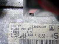
My sensor was marked with Bosch Germany, 485450A and 0 281210238. This particular sensor has the plug directly on the sensor rather than having the extension wire and then the plug.
My ECU is MEH73H4F001
Resistance at the sensor was 931 ohms. While measuring resistance, metal brought very near the sensor would make big changes to the resistance.
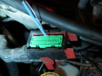
The two sensor wires are a slightly twisted red and white pair. Taking both of the ECU plugs off it was fairly easy to work out the twisted red and white were in the plug nearest the windscreen. I then used a Light emitting diode or LED with a resistor in series connected to the battery to trace the wires to the correct part of the plug. I suppose any old bulb would have done the job but if I messed things the higher current could have damaged something somehow.
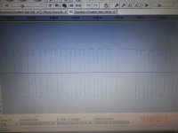
I made up a test lead from an audio cable that would fit into my lap top and used the wires from a diode for the ECU test points. The resistance at the end of my cable was 928ohms. Using freeware audacity sound editing software when I cranked the engine with the starter I got a solid block of pulses which I was able to slow down with the editing software to reveal the square wave the sensor was producing.")
http://sourceforge.net/projects/audacity/
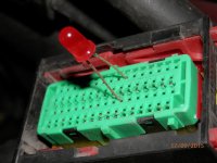
The sensor was able to pulse a LED even when it had the resistance in series quite easily. (my diy test LED with the resistor, glows visibly when on 12V - the idea being to have a test method that draws very little current)
The A/C voltage was 3.49V
I thought this would be an interesting thing to do.
My sensor is the two wire inductance or coil of wire type. A three wire sensor would need a different testing arrangement because it has built in electronics which have to be fed with a reference voltage.
My sensor was marked with Bosch Germany, 485450A and 0 281210238. This particular sensor has the plug directly on the sensor rather than having the extension wire and then the plug.
My ECU is MEH73H4F001
Resistance at the sensor was 931 ohms. While measuring resistance, metal brought very near the sensor would make big changes to the resistance.
The two sensor wires are a slightly twisted red and white pair. Taking both of the ECU plugs off it was fairly easy to work out the twisted red and white were in the plug nearest the windscreen. I then used a Light emitting diode or LED with a resistor in series connected to the battery to trace the wires to the correct part of the plug. I suppose any old bulb would have done the job but if I messed things the higher current could have damaged something somehow.
I made up a test lead from an audio cable that would fit into my lap top and used the wires from a diode for the ECU test points. The resistance at the end of my cable was 928ohms. Using freeware audacity sound editing software when I cranked the engine with the starter I got a solid block of pulses which I was able to slow down with the editing software to reveal the square wave the sensor was producing.
http://sourceforge.net/projects/audacity/
The sensor was able to pulse a LED even when it had the resistance in series quite easily. (my diy test LED with the resistor, glows visibly when on 12V - the idea being to have a test method that draws very little current)
The A/C voltage was 3.49V
Attachments
Last edited: