Hiya People this is my little guide for a locking system from ultimate car parts for a Punto Mk2 3 door link below ( ill add some photos later)
http://www.ultimatecarparts.co.uk/remote-car-alarm-immobiliser-latest-2010-anti-hijack-p-118.html
i got this alarm system as i didnt want to put my key in the door anymore as it is starting to damage my key so i got this thinking it would be easy and so i have now made a guide.
i have read that most puntos have a negative locking system so i got out my Haynes manual and checked the wiring diagram to make sure which in the MK2 it is.
first of all DISCONNECT THE BATTERY TERMINALS as you dont wanna go blowing fuses or worse electrocution
second
you need to get into under the steering wheel you need to undo a few allen key screws to acces this then take out the bit which is next to your right knee its 2 simple plastic screws i used a small flat head screw driver for undoing both as i didnt have the right allen key at the time
Thirdly
first of all i have connected the Red Wire to the ignition barrel Red Wire Which is the live wire as i blew a fuse connecting it to the radio live wire (My Bad:bang
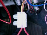
The Black Wire needs to go to a grounding point the one is used is under the steering wheel i used a pair of pliars to undo the bold but it a i want to say 11mm spanner (ill Measure it at some point and update it ) what i did as i had some spare 12v wire so i cut it down and used that to make a little extsion so i could position the box better and so used a 15amp terminal block or connector block which i got from wilkos for 68p
(before people start commenting i know i used a red wire to loop it round it so i could put the yellow and yellow and black wires in the the other side of the terminal block too save on connection and cutting different wires p.s ignore in the picture that there is a orange wire in there dont do this i did this then took the photo and then realised what i had just wired in and took them out)

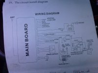
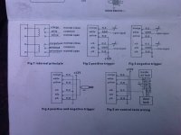
i have included both wiring diagrams below is the wiring diagrams for the alarm system.


as you can see me need diagram number 3 as we have a negative trigger system so
Wires and there places
Red +12v (it connects to a power wire Red Wire)
Black (ground wire any grounding point e.g. the cars shell)
Yellow (needs to be grounded)
Yellow & Black (needs to be grounded)
White (this wire is on the main block this goes to the ACC(orange wire in the ignition barrel)
White (the open signal from the central locking line to the Black & Blue)
White & Black (the close signal which connects to the White & Black Wire in the fuse box)
Blue (grey and Brown)
Pink (Siren live wire the other siren wire goes to a grounding point)
Green( only connect if you have a solenoid to release the boot)
DO NOT CONNECT THE FOLLOWING WIRES
Orange on the central locking line
Orange and black on the central locking line
3 Yellow wires on the Main connecter
(there are technicially 5 yellow wires 1 for the immobiliser that is included in the kit that i was told not to connect up, 2 that apparently do nothing and the other 2 on the central locking line which are yellow and yellow & black which ARE needed)
I will Udate this guide later on today or tomorrow as i will take some photos too
http://www.ultimatecarparts.co.uk/remote-car-alarm-immobiliser-latest-2010-anti-hijack-p-118.html
i got this alarm system as i didnt want to put my key in the door anymore as it is starting to damage my key so i got this thinking it would be easy and so i have now made a guide.
i have read that most puntos have a negative locking system so i got out my Haynes manual and checked the wiring diagram to make sure which in the MK2 it is.
first of all DISCONNECT THE BATTERY TERMINALS as you dont wanna go blowing fuses or worse electrocution
second
you need to get into under the steering wheel you need to undo a few allen key screws to acces this then take out the bit which is next to your right knee its 2 simple plastic screws i used a small flat head screw driver for undoing both as i didnt have the right allen key at the time
Thirdly
first of all i have connected the Red Wire to the ignition barrel Red Wire Which is the live wire as i blew a fuse connecting it to the radio live wire (My Bad:bang
The Black Wire needs to go to a grounding point the one is used is under the steering wheel i used a pair of pliars to undo the bold but it a i want to say 11mm spanner (ill Measure it at some point and update it ) what i did as i had some spare 12v wire so i cut it down and used that to make a little extsion so i could position the box better and so used a 15amp terminal block or connector block which i got from wilkos for 68p
(before people start commenting i know i used a red wire to loop it round it so i could put the yellow and yellow and black wires in the the other side of the terminal block too save on connection and cutting different wires p.s ignore in the picture that there is a orange wire in there dont do this i did this then took the photo and then realised what i had just wired in and took them out)

i have included both wiring diagrams below is the wiring diagrams for the alarm system.


as you can see me need diagram number 3 as we have a negative trigger system so
Wires and there places
Red +12v (it connects to a power wire Red Wire)
Black (ground wire any grounding point e.g. the cars shell)
Yellow (needs to be grounded)
Yellow & Black (needs to be grounded)
White (this wire is on the main block this goes to the ACC(orange wire in the ignition barrel)
White (the open signal from the central locking line to the Black & Blue)
White & Black (the close signal which connects to the White & Black Wire in the fuse box)
Blue (grey and Brown)
Pink (Siren live wire the other siren wire goes to a grounding point)
Green( only connect if you have a solenoid to release the boot)
DO NOT CONNECT THE FOLLOWING WIRES
Orange on the central locking line
Orange and black on the central locking line
3 Yellow wires on the Main connecter
(there are technicially 5 yellow wires 1 for the immobiliser that is included in the kit that i was told not to connect up, 2 that apparently do nothing and the other 2 on the central locking line which are yellow and yellow & black which ARE needed)
I will Udate this guide later on today or tomorrow as i will take some photos too

