This job requires work on the vehicles electrics and might void your warranty And if done incorrectly could start a Fire
thats the disclamer out of the way
Gone are the Days when you'd just scotch hook the trailing end of the 7 way cable to the loom with the bulb failure system and Fiats notoriously small cables it cant be done for fear of melting the loom and having the check Bulb light come on every time you use the socket....
you dont need a towbar to always need road lights if you use a strap on cycle rack for example that blocks vision of your road lights you will need a light board for example..
I have left out the towbar bracket fitting instructions as these are specific to the brand of towbar you have bought
The stuff you will need are
12N socket and mounting hardware
2 mtrs of 7 core wire
1.5 to 2 mtrs of 2 core twin 1.5mm is fine
a Reel of Single core >than 20Amp rated cable
7 scotch hooks
7 Way Bypass relay
a blue eyelet crimp
Fuse holder and associated spade crimps
Soldering iron,
Screwdriver,
wire cutters,
stanly knife
wire strippers
insulating tape
Cable ties..
A working lighting board is handy to test
I think thats it......
Mine is fitted on an Active, GP Active's dont have the boot mounted fuse board regardless of spec level you need a nice constant juicy supply from somewhere not a switched feed from the ignition as you wont be able to leave your hazards on for example with the keys removed ..
On the higher spec levels it should be possible to take a feed from the boot mounted fuse board however on mine it was taken from the front glove box fuse board supply tail. But could also be taken off the battery and run through the grommet under the front scuttle panel on the passengers side (uk)
Mine was connected after first removing the battery clamps for safety..
You need to strip about 8mm of insulation off the "tail" then tin the wire with solder
next strip the end of a short bit of 20 Amp wire and twist a loop of bare wire round the tinned section of stripped wire and tin and solder together to form good joint.
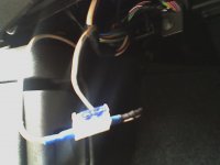
Wrap the section well with tape this will support the joint and insulate it to prevent it from shorting.. at the end of the short length you need to fit a fuse holder I used a blade holder which was connected using 2 insulated crimp connections (leave the fuse out for now) next you need to run the rest of the 20 amp wire to the back of the car boot... to the left this is the main power feed to power all the road lights...

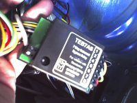
Once in place you need to wire the relay unit this is about the size of a fag packet and mine included a pizzo sounder to let you know the indicators are functioning on the trailer.....
the relay comes with 7 wires on one end and a row of screw terminals on the other.. along with 2 other screw terminals marked 12V this is where you connect your feed from the fuse board and the other TT this is an option for fitting a warning light to the dashboard which flashes in time to the indicators doing the same job as the pizzo sounder

the fixed wires are to be scotch hooked onto the loom in the correct order as per below with the right indicator and side light been connected via the length of 2 core across the boot behind the plastic trim boot liner remember which colour you used for each eg red for indicator and black for sidelight and through crimp these to the corresponding : lead on the relay (green for the indiactor and Brown for the sidelight)
Pin no)Relay & Socket colour = Lamp= Car loom colour
1)Yellow = Left Hand Indicator = Pink
2)Blue = Rear Fog lamp = Gray
3)White = EARTH = ((To chassis))
4)Green = Right Hand Indiactor = Pink with black stripe
5)Brown = RH sidelight & No plate lamp = Yellow with black stripe
6)Red = Brake lights = Green with white stripe
7)Black = Left Sidelight and no plate lamp = Green with Yellow stripe
You will see there is no No3 on the relay as pin 3 is Earth...
The white trailing wire needs to be left disconnected at the moment
next fit the socket to the towbar (these are usually pre wired) strip about 30cm/ 12" of insulation off and sepperate out all the wires and strip the tips of the individual cores 5mm should be ample and to be really fussy tin these (it makes it far easyer to fit into the screw treminals and reduces the chance of a short across the road lights)
Dont tin the white wire....
now for these 2 white wires you haven't done anything with yet......
stip both twist together and fit an Eyelet crimp and fix to the chassis of the car (there are plenty of screwholes just dont use one with a plastic insert or you wont get a connection)
once done tidy up the wires and tie them in place to prevent any strain on the scotch hooks. and cast your eye over looking for any silly mistakes
once satisfied put a 20 amp fuse in the holder and connect the battery if it blows immediately you have a short somewhere..
next plug in a lighting board and check the function of the lights
thats the disclamer out of the way
Gone are the Days when you'd just scotch hook the trailing end of the 7 way cable to the loom with the bulb failure system and Fiats notoriously small cables it cant be done for fear of melting the loom and having the check Bulb light come on every time you use the socket....
you dont need a towbar to always need road lights if you use a strap on cycle rack for example that blocks vision of your road lights you will need a light board for example..
I have left out the towbar bracket fitting instructions as these are specific to the brand of towbar you have bought
The stuff you will need are
12N socket and mounting hardware
2 mtrs of 7 core wire
1.5 to 2 mtrs of 2 core twin 1.5mm is fine
a Reel of Single core >than 20Amp rated cable
7 scotch hooks
7 Way Bypass relay
a blue eyelet crimp
Fuse holder and associated spade crimps
Soldering iron,
Screwdriver,
wire cutters,
stanly knife
wire strippers
insulating tape
Cable ties..
A working lighting board is handy to test
I think thats it......
Mine is fitted on an Active, GP Active's dont have the boot mounted fuse board regardless of spec level you need a nice constant juicy supply from somewhere not a switched feed from the ignition as you wont be able to leave your hazards on for example with the keys removed ..
On the higher spec levels it should be possible to take a feed from the boot mounted fuse board however on mine it was taken from the front glove box fuse board supply tail. But could also be taken off the battery and run through the grommet under the front scuttle panel on the passengers side (uk)
Mine was connected after first removing the battery clamps for safety..
You need to strip about 8mm of insulation off the "tail" then tin the wire with solder
next strip the end of a short bit of 20 Amp wire and twist a loop of bare wire round the tinned section of stripped wire and tin and solder together to form good joint.
Wrap the section well with tape this will support the joint and insulate it to prevent it from shorting.. at the end of the short length you need to fit a fuse holder I used a blade holder which was connected using 2 insulated crimp connections (leave the fuse out for now) next you need to run the rest of the 20 amp wire to the back of the car boot... to the left this is the main power feed to power all the road lights...

Once in place you need to wire the relay unit this is about the size of a fag packet and mine included a pizzo sounder to let you know the indicators are functioning on the trailer.....
the relay comes with 7 wires on one end and a row of screw terminals on the other.. along with 2 other screw terminals marked 12V this is where you connect your feed from the fuse board and the other TT this is an option for fitting a warning light to the dashboard which flashes in time to the indicators doing the same job as the pizzo sounder

the fixed wires are to be scotch hooked onto the loom in the correct order as per below with the right indicator and side light been connected via the length of 2 core across the boot behind the plastic trim boot liner remember which colour you used for each eg red for indicator and black for sidelight and through crimp these to the corresponding : lead on the relay (green for the indiactor and Brown for the sidelight)
Pin no)Relay & Socket colour = Lamp= Car loom colour
1)Yellow = Left Hand Indicator = Pink
2)Blue = Rear Fog lamp = Gray
3)White = EARTH = ((To chassis))
4)Green = Right Hand Indiactor = Pink with black stripe
5)Brown = RH sidelight & No plate lamp = Yellow with black stripe
6)Red = Brake lights = Green with white stripe
7)Black = Left Sidelight and no plate lamp = Green with Yellow stripe
You will see there is no No3 on the relay as pin 3 is Earth...
The white trailing wire needs to be left disconnected at the moment
next fit the socket to the towbar (these are usually pre wired) strip about 30cm/ 12" of insulation off and sepperate out all the wires and strip the tips of the individual cores 5mm should be ample and to be really fussy tin these (it makes it far easyer to fit into the screw treminals and reduces the chance of a short across the road lights)
Dont tin the white wire....
now for these 2 white wires you haven't done anything with yet......
stip both twist together and fit an Eyelet crimp and fix to the chassis of the car (there are plenty of screwholes just dont use one with a plastic insert or you wont get a connection)
once done tidy up the wires and tie them in place to prevent any strain on the scotch hooks. and cast your eye over looking for any silly mistakes
once satisfied put a 20 amp fuse in the holder and connect the battery if it blows immediately you have a short somewhere..
next plug in a lighting board and check the function of the lights

