hi i'm thinkin of doin a 1.2 16v conversion on a cinqueento i hav a mk1 punto sporting sat on my drive thats a cat c i was going to put it bk on the road but was given a cinq the other day and i lyk them more so a conversion would make the best from both cars anyways the mechanics ent going to b a prob as have done a few str8 swops on puntos n cinquecentos b4 its the wirering that has me stumped dos any1 have any advice on how to make the cinq loom and the punto loom as 1???


You are using an out of date browser. It may not display this or other websites correctly.
You should upgrade or use an alternative browser.
You should upgrade or use an alternative browser.
Technical 16v cinq conversion
- Thread starter azz
- Start date
Currently reading:
Technical 16v cinq conversion
having both cars sat there should make it quite doable, as for merging the two looms - again, with some thought and some diagrams it should well be possible.
the mk1 sportings ecu is of a similar generation and type to the cinq ecu, so the wiring is probably quite compatible to begin with. you need pinouts of both ECUs.
here is the cinq ecu pinouts, colours refer to my (1995) cinq sporting.
the mk1 sportings ecu is of a similar generation and type to the cinq ecu, so the wiring is probably quite compatible to begin with. you need pinouts of both ECUs.
here is the cinq ecu pinouts, colours refer to my (1995) cinq sporting.
Code:
wiring loom, ecu connector.

pin	colour		function					notes

1	white/green	coil pack 1
2	green		idle controller
3	blue/yellow	idle controller
4	blue/red	fuel injection main relay (winding input)
5
6	grey/red	injector warning light
7
8	green		air con
9
10	l blue/ blue	diagonostic socket
11	blue/red	TDC sensor
12	brown/green	lambda
13	purple/white	CTS
14	l blue/black	5v supply for MAP and TPS
15	white/red	diagnostic socet
16	black		CTS, IAT, MAP, Lambda, DS, main earth
17	green/black	lambda
18	pink/black	injector
19	l blue/red	coil pack 2
20	blue/white	idle controller
21	white		idle controller
22	orange/black	canister purge solenoid
23	black/purple	fuel pump relay (winding input)
24	yellow		air con
25
26	orange		fuel pump relay (winding earth)
27
28	yellow/black	TDC sensor
29	blue/yellow	lambda
30	pink		TPS
31	purple		IAT
32	yellow/red	MAP sensor (signal)
33
34	grey/black	main ecu earth


Number 	Description 	Component / Function Notes
1 	Output 		Ignition Coil 1 Cylinders 1+4
2 	Output 		Idle Control Stepper Motor Phase B
3 	Output 		Idle Control Stepper Motor Phase D
4 	Output 		Central Power Relay (Power-Latch) Power to RAM
5 	Input 		Automatic Gearbox ECU input Only on Version CA
6 	Output 		ECU Warning Lamp Activated on -Vbatt
7 	Input / Output 	Immobilizer (If Present, otherwise NC) Bidirectional
8 	Input 		Air Conditioner Relay on (+) Activated on +Vbatt
9 	NC 		Not Connected Not Connected
10 	Input 		Serial Line L Unidirectional line (FLT->ECU)
11 	Input 		TDC / RPM Sensor Signal Negative
12 	Input 		Lambda Sensor Signal Negative
13 	Input 		Water Temperature Sensor Signal
14 	Output 		Sensor +5v Line 5 volt DC
15 	Output 		Serial Line K Bidirectional line (FLT->ECU)
16 	Power 		Signal Grounds In Wiring Loom
17 	Power 		Primary Ground Engine Ground
18 	Output 		Fuel Injector Controls SPi Unit
19 	Output 		Ignition Coil 2 Cylinders 2+3
20 	Output 		Idle Control Stepper Motor Phase A
21 	Output 		Idle Control Stepper Motor Phase C
22 	Output 		Charcoal Canister Multifunction Valve
23 	Output 		Engine Speed Limiting (Fuel Pump) Relay Fuel Pump / Injector / Canister / Coils / Lambda
24 	Output		Air Conditioner Relay on (-) Activated on Gnd
25 	NC 		Not Connected Not Connected
26 	Input 		Ignition in "On" Position
27 	NC 		Not Connected Not Connected
28 	Input 		TDC / RPM Sensor Signal Positive
29 	Input 		Lambda Sensor Signal Positive
30 	Input 		Throttle Position Sensor Signal
31 	Input 		Air Temperature Sensor Signal
32 	Input 		MAP Sensor Signal
33 	NC 		Not Connected Not Connected
34 	Power 		Secondary Ground Engine Ground
35 Power Positive feed from Main Relay Positive out from ECU Relay / Power-Latchmine uses a MegaSquirt ECU, so i just hacked off the old ECU connector, and using a few sources, came up with the above table - and used that to wire the new one in.
Hi
This is how I have worked out he megasquirt to punto loom.
Is there an expert sparks who can check it for me:worship:
Will help future megasquirters no end.
Ignore the light green and light blue wires on stepper ICT as these only apply to the mk2 megasquirt with a v3 board. I’m using a Mk1 with v3 board and 29v firmware. This utilises pin 36 and pin 31 for coils.
Wiring for a v3 megasquirt board – with wasted spark upgrade using pin 36 for coil A and pin 31 for coil B.
I think..
Mega punto ecu connector
Pin 20 > pin 31 intake air temp sensor
Pin 21 > pin 13 coolant temp sensor
Pin 22 > pin 30 throttle potentiometer (?uncertain on this)
Pin 23 > pin 29 ( could be pin 12 but I think thats an earth?) lambda
Pin 24 > pin 11 (or should this be pin 28? Tach. crank take off, tdc.)
Pin 25 ignore
Pin 26 > pin 14 (please check?)
Pin 27 ignore
Pin 28 > pin 26 link to pin 14 to give + out to injectors
Pin 29 ignore
Pin 30 > relay for Fidle (no direct correspondence but could connect to stepper wiring which will be connected to a bosch or pwm idle valve?)
Pin 31 > pin 1 (coil b?) This is the wasted spark upgrade out. Not shown on v3 standard diagram.
Pin 32 , 33, 34, 35 > pin 18 injectors
Pin 36 > pin 19 (coil a?)
Pin 37 > pin 26 (live in on spi but not on sporting so sporting would need this added to car loom?)
Mega punto ecu connector
Pins 1 through to 6 ignore
Pin 7 > pin 28 (or should this be 11?) tdc tacho sensor
Pin 8,9,10,11 and 19 to > pins 17 and 16 bridged
Pins 12 to 18 ignore
Phew
If anyone can help me with this I would be very grateful – I’ll even pay !
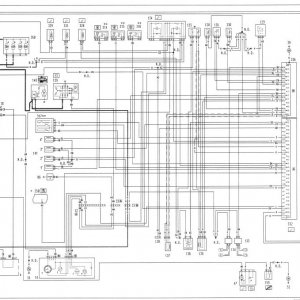
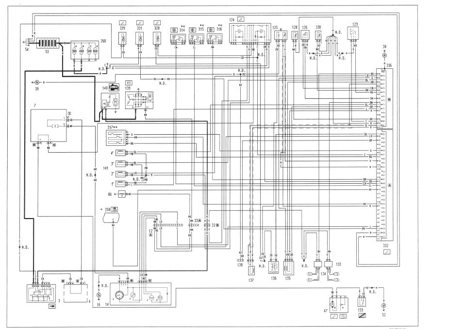
I have included v3 wiring diagram and a punto diagram. I’m working from the Haynes diagram
-------------------------------------------------------------------
And
Thanks:worship: :worship:

from; https://www.fiatforum.com/cinquecento-seicento/88873-megasquirt.html it is talking about making a connector to go from punto sporting loom to ms ecu, but you should be able to untangle it and decode the ECU pinout. i dont have a larger copy of the pinout image, maybe dave does?
that was what i was suggesting
(was trying to add some context the post with all the pin x to pin y stuff in it )
(was trying to add some context the post with all the pin x to pin y stuff in it )
Last edited:
i'm starting to tear down the punto to day got alot of wire to go though but hoping to have it in n working by next weekend i'll try putting sum pics up n if anyone has any advice that would be gr8 i carnt w8 4 that 85bhp :slayer:
but hoping to have it in n working by next weekend i'll try putting sum pics up n if anyone has any advice that would be gr8 i carnt w8 4 that 85bhp :slayer:Use the Punto clutch and flywheel.
i still need help with the wiring :bang: i've been told to just cut the block thats on the fire wall and extend the wires to the cinq block at the front of the car just need to no wot wire dos wot for the the cinq and the punto theres 13 wires on the punto and 8 on the cinq and the engine i'm using has all new belts plugs leads ect ect as i was gonna put oit on the road and it only has 46000 on the clock so its sweet as :slayer:
pretty much all the info you need is already in this thread, anything you shuold be able to work out by tracing the wires and probing with a multimeter
- Joined
- Feb 16, 2005
- Messages
- 5,983
- Points
- 988
what connector block do you mean?
where the body and engine looms join
- Joined
- Feb 16, 2005
- Messages
- 5,983
- Points
- 988
Refered to as the D4 connector afair.
I know it carries oil pressure line, power for injectors, and some other stuff. I have slimmed mine down to 2 wires, the rest i didn't need!!!!
I am uploading stuff for you at the moment to help.
I know it carries oil pressure line, power for injectors, and some other stuff. I have slimmed mine down to 2 wires, the rest i didn't need!!!!
I am uploading stuff for you at the moment to help.
Similar threads
- Replies
- 2
- Views
- 284