OP
OP
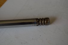
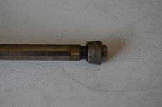
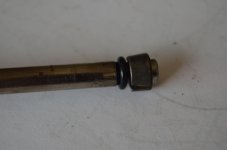
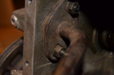
Hope you can find the right fuel pump push rod otherwise you are short of a squirt of gas ?
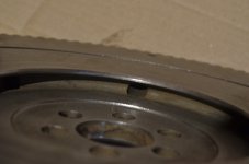
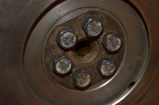
Probably some syndrome I have but I always arrange those push rod tubes in the way you have for the symmetry and always keep twisting them as you torque down the head to ensure that the seals seem happily seated and no pinching. So the question is was the engine originally designed to allow a small amount of oil to flow through those small cut outs from oil puddling in the depressions to lube the cam followers with the bulk of the oil flow going down the deeper central cavity where the oil feed pipe runs up to the rockers.
How wonderful it would be if the original designers of the 500 were available to answer questions about their designs.
...exactly what I did with the seals but accidentally in my case, rather than a search for perfection or mechanical awareness, because it only occurred to me halfway through tightening to swivel the tubes into alignment.

I hadn't checked out the fit of that spacer on the rod yet. The rod is the one that came with the engine so I guess someone's been here before. This engine had definitely been used on a Fiat 500 before I bought it because the gearbox already had the correct driveshafts. I could rob the correct rod off another spare engine but to get it going I think I'll use the thin spacer.
I'm assuming that there is a surplus of oil-flow to the head which means that, (on level ground), the four shallow depressions abutting the tops of the tubes will be permanently flooded and overflowing oil down them. When you look closely at the casting, each depression is bounded by a slightly raised barrier on all sides. Going steeply uphill or downhill might have temporarily slightly deprived either of the two exhaust cams of oil when, as you say, the bulk of the oil would run to the central drain.