Technical Confused about timing marks

Currently reading:
Technical Confused about timing marks

NutGL

Member
Joined
Jun 9, 2025
Messages
10
Points
52
Location
Texas, USA
Hi everyone.
I recently bought a 1971 Fiat 500 F in running condition but that was idling poorly. The engine would run very rough and you could see heavy, black smoke coming out from the exhaust all the time.

I went ahead and took the carburetor apart to find out some parts and adjustments were needed.
I placed the carburetor back on the car, I turned on the engine and I realized the exhaust black smoke disappeared completely,. I could see that the engine idled better too but it was still giving me some hiccups here and there so I thought it would be a good idea to tinker with tappet clearance, breaker points gap and correcting the timing.

I found out that according to several videos I saw, my distributor rotor was placed 180 degrees off pointing away from the engine block, so I took the whole distributor out and placed it with the rotor pointing towards the engine making sure sparkplugs wires would be swapped to the right position in the distributor cap. I found one that the lead position on the distributor cap are factory marked as cylinder 1 sparkplug corresponding to the 180 position away from the engine block, but I still decided to switch the sparkplug wires position according to what I saw from other videos.
Then, my confusion continued. I've found videos, posts and info on the Haynes and other workshop manuals mentioning two different timing marks to look for but it turns out my car has them both. I don't really know which one to use to set up my static timing. I've been using both and neither of them make my car starts again. I don't know if it's related with the way in which I placed my distributor back in the engine case or something else, but I cannot make tt run again.
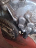
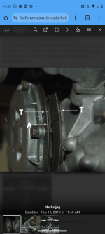
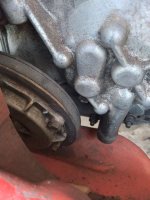
I have posted two photos, one of the raised timing mark in the oil cover and another photo showing a notch over the rim of the pulley. I painted the notch over the pulley rim white for easy identification. You will see a second line to the right which corresponds to 10 degrees before TDC measuring 13mm from the factory notch.

Can you guys please tell me which mark I should be aligning with the arrow in my engine case to set up the static timing in my car? Is it the raised line in the oil cover or the notch in the pulley rim?
 

Attachments

  • 20250706_133327.jpg
    20250706_133327.jpg
    58.6 KB · Views: 29
  • 20250706_133306.jpg
    20250706_133306.jpg
    42.9 KB · Views: 19
Here is a video of my car. I have the 595cc engine which has 2 timing marks but the principle is the same. There is a line on the belt cover and an arrow on the oil pump cover. When the arrow points at the line, the pistons are at top dead centre. You want your spark to occur 10° ahead of TDC at tick over. 10° is 13mm along the circumference of the pulley. Some people mark a line on the pulley 13mm from the embossed line.

 
Here is a video of my car. I have the 595cc engine which has 2 timing marks but the principle is the same. There is a line on the belt cover and an arrow on the oil pump cover. When the arrow points at the line, the pistons are at top dead centre. You want your spark to occur 10° ahead of TDC at tick over. 10° is 13mm along the circumference of the pulley. Some people mark a line on the pulley 13mm from the embossed line.

Thanks Smart 51. So if the raised line is the one used for TDC, what is that notch on the pulley rim used for? And why the Haynes manual mentions it?
 
Thanks Smart 51. So if the raised line is the one used for TDC, what is that notch on the pulley rim used for? And why the Haynes manual mentions it?
If the notch is 13mm (just over 1/2") away from the line, it is likely that a previous owner made it themselves for convenience. When the arrow on the oil pump cover points to a spot 13mm away from the line on the pulley, the pistons are 10° BTDC, which is where the points should open. If setting the static timing with a light bulb, you turn the engine to this point, then turn the distributor until the lightbulb just turns on.
 
Here is a video of my car. I have the 595cc engine which has 2 timing marks but the principle is the same. There is a line on the belt cover and an arrow on the oil pump cover. When the arrow points at the line, the pistons are at top dead centre. You want your spark to occur 10° ahead of TDC at tick over. 10° is 13mm along the circumference of the pulley. Some people mark a line on the pulley 13mm from the embossed line.

Have you got a '500' engine in your car or a '126' (652cc) engine in it? The 500 engine number (just by the fuel-pump) will start with "110"---a '126'engine will start with "126". I ask this because the timing marks are slightly different between the 2 engines. As "Smart51" quite correctly points out, on the 500 the timing mark (the "notch") on the crank-pulley when lined up with the mark on the timing-chain cover will indicate that the engine is at TDC when they align. As idle timing is 10 deg BTDC, make a mark on the pulley 13mm TO THE RIGHT of the timing 'notch' on the pulley (the engine turns clockwise). This will be your idle timing mark.
On the '126' engine, there are normally 2 marks on the timing-chain cover---the 1st mark will be your 10deg BTDC timing mark. be also aware that on both the 500 and 126 engines, number 1 cylinder is at the rear of the car (but the front of the engine).
Whilst you working on the engine, it will be sensible (and wise) to clean the oil-filter. The 500,a (long with the 126, 600 and 850 engines), all have centrifugal oil-filters. On the 500 and 126 engines it is the alloy cover on the front of the crankshaft pulley---although a tad tedious, it CAN be removed/re-fitted with the rear cross-member still in situ. When you have removed it (have a container under the pulley as some oil will come out) the inside will be covered in what looks like rubber---that is the gunge that has come out of your oil! Clean it all out, along with the gunge that will be on the inside of the pulley, and then refit the cover,with a new seal. When it comes to re-fitting the cover, it will only go on in one position---the fitment holes are not equi-distant. The reason for this is that the timing mark (which is also often on the cover) will go back in the correct place. If in doubt, mark the alloy cover and the pulley with 'Tipex' (or similar)
 
The best way to do this is to start again making a mark on the pulley 13mm to the right, (ie clockwise) from the raised mark cast in the oil filter cover.

Manually turn the engine clockwise until that mark is exactly aligned with the arrow cast into the timing cover.

Having removed the distributor-cap, the points should be just opening, which you can test in with a lamp as previously described.

You can loosen the distributor, and rotate it slightl to get to that "just opening" point, and then secure it.

All of this assumes you have he points gap right and the rotor arm pointing to the correct cylinder.

If you are happy that you are at this stage, but the engine won't start, swap round the two plug leads and try again.
Thanks a lot for the tip. I've been confused mostly by the fact different people seems using different reference marks. As a matter of fact, the first thread I took as reference was this one here:

As you can tell, this person uses the notch at the pulley rim (marked as T). The difference with mine is that my pulley notch is not lined up with the raised mark on the cover as the one of this guy (please see photo) could it be that previous owner didn't bolt that cover in the right position ending up with the TDC raised mark on the cover not being lined up with my pulley notch? (Second photo attached is my car) And again, as you can see, the raised mark painted in white for easy identification is not matching with any notches as in the guy's thread.
 

Attachments

  • Screenshot_20250707-143314.png
    Screenshot_20250707-143314.png
    1.3 MB · Views: 11
  • 20250706_133327.jpg
    20250706_133327.jpg
    58.6 KB · Views: 11
Thanks a lot for the tip. I've been confused mostly by the fact different people seems using different reference marks. As a matter of fact, the first thread I took as reference was this one here:

As you can tell, this person uses the notch at the pulley rim (marked as T). The difference with mine is that my pulley notch is not lined up with the raised mark on the cover as the one of this guy (please see photo) could it be that previous owner didn't bolt that cover in the right position ending up with the TDC raised mark on the cover not being lined up with my pulley notch? (Second photo attached is my car) And again, as you can see, the raised mark painted in white for easy identification is not matching with any notches as in the guy's thread.
I would suggest that mark "A" is your 10 deg BTDC ,and mark "T" is your TDC mark as it basically lines up with the pulley 'notches'. You CANNOT fit the oil-filter cover (with the timing mark) onto the pulley in the wrong place---the bolt holes just will NOT align. Turning the distributor clockwise RETARDS the ignition, turning it ANTI clockwise ADVANCES the ignition. If I remember correctly, you don't have a lot of advance/retard movement of the distributor on a 500, so as Peter has suggested have the distributor in a position where the points are JUST opening. For sheer convenience, I turn the engine (as again suggested by Peter) so that the first 'notch'on the crank-pulley is aligned with the timing mark on the timing-chain cover, and then fit the distributor back in with the rotor-arm pointing noth or south (easy to remember for future settings) in with.The distributor body position should basically be in a position where the wire to the negative terminal (-- or 1) on the coil is pointing away from the engine (south). Connect a 12 volt test-lamp to the negative terminal on the coil and to a good earth. Remove the "king" lead from the coil (so the engine cannot just burst into life---fair buggers the fingers) and turn on the ignition. If the test-lamp lights up, turn the distributor CLOCKWISE until the light goes out, and then SLOWLY, ANTI-clockwise until the light comes back on. If the light is NOT on, turn the distributor ANTI-clockwise until the light comes on. Tighten the securing nut for the distributor and, with the ignition still on, turn the engine (by hand!) 1 complete revolution until the timing marks become aligned and then check when the test-light come on----that is your timing point.
If your condenser is mounted on the coil, may I suggest that you try and obtain a"Competition" condenser from"SWIFTUNE"---these condensers have a long supply lead and a long earth lead, so that it can be mounted up by the coil and away from the heat of the "cooling" air coming from the engine---modern, pattern condensers do NOT like heat! If you combine the sound advice from Peter (Fiat500) and "smart51"along with these musings, you should have no problem setting up the ignition timing.
 
Thanks a lot for the tip. I've been confused mostly by the fact different people seems using different reference marks. As a matter of fact, the first thread I took as reference was this one here:

As you can tell, this person uses the notch at the pulley rim (marked as T). The difference with mine is that my pulley notch is not lined up with the raised mark on the cover as the one of this guy (please see photo) could it be that previous owner didn't bolt that cover in the right position ending up with the TDC raised mark on the cover not being lined up with my pulley notch? (Second photo attached is my car) And again, as you can see, the raised mark painted in white for easy identification is not matching with any notches as in the guy's thread.
As with Tom (@the hobbler ) above; the cover can't be put on incorrectly as the screws are staggered.
The mark on that pulley"A" appears to be on the right place for 10 degrees TDC. Ignore mark "T"
Make a white mark at "A" on your pulley, (13mm clockwise from the white, raised mark) and align with the raised arrow on the timing chain cover; your engine will have both pistons at the point for the spark to fire.
 
Last edited:
I would suggest that mark "A" is your 10 deg BTDC ,and mark "T" is your TDC mark as it basically lines up with the pulley 'notches'. You CANNOT fit the oil-filter cover (with the timing mark) onto the pulley in the wrong place---the bolt holes just will NOT align. Turning the distributor clockwise RETARDS the ignition, turning it ANTI clockwise ADVANCES the ignition. If I remember correctly, you don't have a lot of advance/retard movement of the distributor on a 500, so as Peter has suggested have the distributor in a position where the points are JUST opening. For sheer convenience, I turn the engine (as again suggested by Peter) so that the first 'notch'on the crank-pulley is aligned with the timing mark on the timing-chain cover, and then fit the distributor back in with the rotor-arm pointing noth or south (easy to remember for future settings) in with.The distributor body position should basically be in a position where the wire to the negative terminal (-- or 1) on the coil is pointing away from the engine (south). Connect a 12 volt test-lamp to the negative terminal on the coil and to a good earth. Remove the "king" lead from the coil (so the engine cannot just burst into life---fair buggers the fingers) and turn on the ignition. If the test-lamp lights up, turn the distributor CLOCKWISE until the light goes out, and then SLOWLY, ANTI-clockwise until the light comes back on. If the light is NOT on, turn the distributor ANTI-clockwise until the light comes on. Tighten the securing nut for the distributor and, with the ignition still on, turn the engine (by hand!) 1 complete revolution until the timing marks become aligned and then check when the test-light come on----that is your timing point.
If your condenser is mounted on the coil, may I suggest that you try and obtain a"Competition" condenser from"SWIFTUNE"---these condensers have a long supply lead and a long earth lead, so that it can be mounted up by the coil and away from the heat of the "cooling" air coming from the engine---modern, pattern condensers do NOT like heat! If you combine the sound advice from Peter (Fiat500) and "smart51"along with these musings, you should have no problem setting up the ignition timing.
Thanks a lot brother. I will definitely take your tips to apply them. Wish me luck 😆
 
As with Tom (@the hobbler ) above; the cover can't be put on incorrectly as the screws are staggered.
The mark on that pulley"A" appears to be on the right place for 10 degrees TDC. Ignore mark "T"
Make a white mark at "A" on your pulley, (13mm clockwise from the white, raised mark) and align with the raised arrow on the timing chain cover; your engine will have both pistons at the point for the spark to fire.
Thanks a lot man!. As you can tell in my photo vs the other member's photo, his raised mark is aligned with the left notch which corresponds to TDC while mine is not.aligned at all, and this is precisely what was giving me the confusion. I believe now, the notch on the pulley rim is just a mark to have a clearer visualization of the TDC spot to be aligned with the different timing marks using the Fiat timing plate tool once in place over the engine case. After reading all of you guys comments, it seems I have to ignore my notch since is not aligned with my oil filter TDC cover raised mark for some reason, but to use this raised mark only as a starting point to create a secondary mark in a clockwise direction 13 mm away and to set my static timing right there.
 
Thanks a lot man!. As you can tell in my photo vs the other member's photo, his raised mark is aligned with the left notch which corresponds to TDC while mine is not.aligned at all, and this is precisely what was giving me the confusion. I believe now, the notch on the pulley rim is just a mark to have a clearer visualization of the TDC spot to be aligned with the different timing marks using the Fiat timing plate tool once in place over the engine case. After reading all of you guys comments, it seems I have to ignore my notch since is not aligned with my oil filter TDC cover raised mark for some reason, but to use this raised mark only as a starting point to create a secondary mark in a clockwise direction 13 mm away and to set my static timing right there.
Correct! )
 
Back
Top