Technical O2 sensor fault

Currently reading:
Technical O2 sensor fault

Too late ?.... No only joking I didn't think so just didn't understand what you meant in your last post??

Cheers

Mark
 
What happened to my post spelling it out?

Oh well

Try again,

meter set to read dc volts, - ve lead touching a good ground point
Unplug the o2 sensor.
Probe the socket that connects to car , you want to probe the heater wire that should be battery voltage.
See if you have battery voltage.
Ignition will have to be on and possibly engine running.

Doing this will check that o2 heater is getting voltage from its fuse , relay and wire.


Trying to find out why you getting code for o2 sensor heater element fault
 
Last edited:
λ (O2) sensor's heater is two wires fed and the signal is returned to ECU with two wires, so it should not be sensitive to battery to boddy earthing, while A LOT of other errors and misbehavior would pop-up.

Here are some info about the λ sensors ...

BRs, Bernie

If someone here helped You fix -or better, understand- your issue, hit the thanks icon @ bottom right corner, it's free and makes us feel helpy ;-)
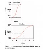
Hi Bernie. I'm feeling a little nervous about this post because you obviously know more about the electronics than I do. However because, with my daughter in law owning a Jazz - and thinking of replacing it with a much newer one - and my interest in the 1.8 i Vtec Civic, I've been looking into air/fuel ratio sensors (also, I believe, called "wide band" O2 sensors) which are used by a lot of these far eastern manufactures. I'm only just starting to get my head round them.

Am I right that the graph you've put up here is for one of these? I ask because it doesn't look anything like what I would expect an O2 sensor output to look like. ie, switching between 0.1 to 0.9 volts. From the little I understand about wide band sensors they are fed with a control voltage around 3 volts and then modulate the current depending on oxygen content in the exhaust gas?

Here's a quite simple article I found about it:
https://www.tirereview.com/air-fuel-ratio-sensors-vs-oxygen-sensors/
I think our wee cars use the older and simpler to understand Oxygen sensors (I say easier to understand because they are what I'm used to) Do the newer Fiats use these wide band sensors?

So, just when you think you understand how something works they throw a "spanner" in the works again! Don't you just love those automotive engineers, always something fascinating and new to explore!
 
@ Jackwhoo: the λ heater is ground controlled by the ECU, positive is (should be) therefore ALWAYS present ! So the diagnostic method you gave is wrong ...

@ Jock: things have to evolve to meet the tighter emission requirements. The "wide band" λ sensor is one of those evolutions. The narrow band doesn't allow a so "fine" tuning as the wide one, its respond curve being more straight. Have a look at the attachment ...

BRs, Bernie

If someone here helped You fix -or better, understand- your issue, hit the thanks icon @ bottom right corner, it's free and makes us feel helpy ;-)
 

Attachments

  • Lambda Wide-vs-Narrow.jpg
    Lambda Wide-vs-Narrow.jpg
    43.6 KB · Views: 316
@ Jackwhoo: the λ heater is ground controlled by the ECU, positive is (should be) therefore ALWAYS present ! So the diagnostic method you gave is wrong ...

Hello Bernie,

Take it easy with your criticism.

I disagree that what I have suggested is wrong;

Yes the ecu grounds a heater wire from o2 sensor to turn it on .

Yes the positive feed to the o2 sensor heater should be there when relay turns it on...........but ........

What if .........

The fuse to o2 sensor heater has blown?

The o2 sensor wiring is damaged somewhere ?

The above two cases will cause o2 sensor heater code.

Trying to help the original poster with an easy test to start with.


Jack
 
Last edited:
Hello Jack,

sorry if you felt my reply as a critic, it was certainly not my intention !!

But the thing is that proving positive is present won't tell anything about the command circuit ... Sure enough, one have to check the fuse(s) and relay (if involved), this is absolute basic checks, isn't it ?
We (at least me) expect a minimum of knowledge from the forumers who post technical questions, the others would probably go directly to the nearest service or call AAA, so we (I) believe the basics has already been done ...

Finally, in order for the heater to heat, we need BOTH positive and negative present at the connector AND the heater itself being not cut/grounded: the very first and only valuable test is to check if those conditions are met.

- check the fuse and the relay (should click at contact on)
- check 12v is present at the λ sensor connector

From there, if everything is ok, one should proceed further by checking for signal wires continuity, connectors etc.

BRs, Bernie
-
 
Hello Jack,

sorry if you my reply as a critic, it was certainly not my intention !!

But the thing is that proving positive is present won't tell anything about the command circuit ... Sure enough, one have to check the fuse(s) and relay (if involved), this is absolute basic checks, isn't it ?
We (at least me) expect a minimum of knowledge from the forumers who post technical questions, the others would probably go directly to the nearest service or call AAA, so we (I) believe the basics has already been done ...

Finally, in order for the heater to heat, we need BOTH positive and negative present at the connector AND the heater itself being not cut/grounded: the very first and only valuable test is to check if those conditions are met.

- check the fuse and the relay (should click at contact on)
- check 12v is present at the λ sensor connector

From there, if everything is ok, one should proceed further by checking for signal wires continuity, connectors etc.

BRs, Bernie
-

Hello,

You said "the diagnostic method you gave is wrong ..."

And now you claim that is not criticising!

All the While what I had posted is correct.
I am fully aware that testing a good live feed at o2 sensor heater is just a first step.

I try not to assume what a poster has already done. Trying to talk the poster step by step through a diagnostic process.
Which is difficult at a distance.


You are very welcome to write out a step by step fault finding procedure for the original poster . encourage him to reply with the readings he gets at each stage etc....
You are very welcome to take over with this fault finding, you have all the diagrams / pin outs , which I do not, so
Over to you Bernie.
I will watch to see what happens with great interest.
 
Last edited:
Hi Jack,

I do realy apologize for having used the "wrong" term about your diagnostic method.
It is indeed the good one to determine wether the positive reaches the connector ! I would just suggest to take the negative directly at the battery post, since another point might be "not so good". Plus: testing voltage with a multimeter is not the best method, due to the extremely high input impedance (hear resistance) the meter draw a very small current that would not be influenced by i.e. a resistive contact. The best, if you use a volt/multi-meter is to measure it (the heater) connected, to have the circuit loaded, OR use a 12V 15W bulb with two test leads ...

Regarding the testing method, it takes years of learning, experiencing, make mistakes before getting the best possible one and I can't teach that in a 5' step by step process.
First question of PCs help-deskers is "is the power plug in the wall socket ?", second is "is that power on that socket ?" This can be applied to the λ sensor problem: is power coming-in ? The rest will vary upon the answer to this very basic test ...

Best regards, and all my apologies once again !!

Bernard.
 
Back
Top