Aladdinvej
New member
- Joined
- Nov 15, 2019
- Messages
- 8
- Points
- 5
This is written via Google translation hope you understand my question.
I have a Fiat Ducato motorhome (Van), year 2019.
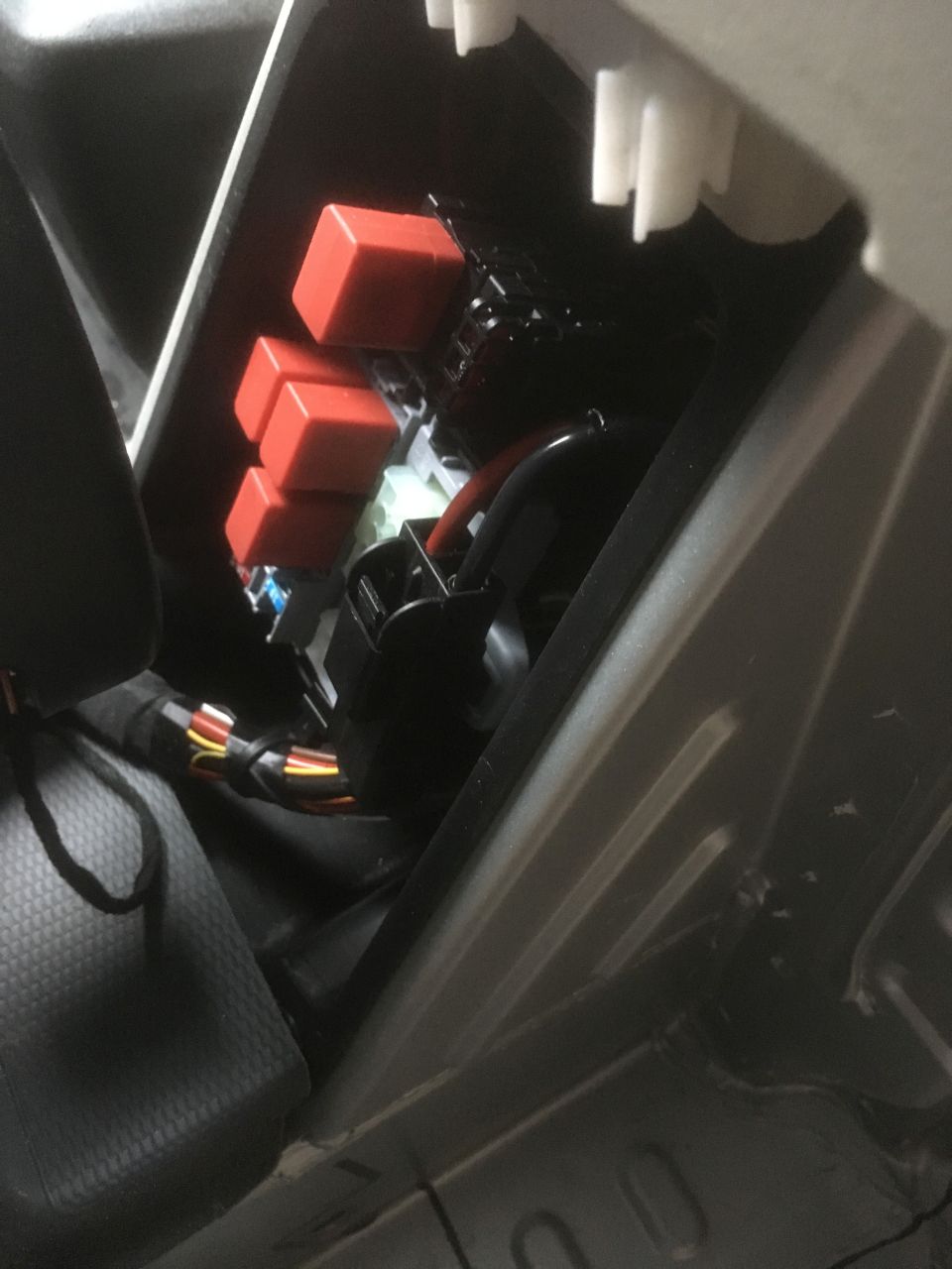
Located at the bottom of pillar B, right passage side there is a multi connector.
Pin 2 should be the 12 volts D+ (motor started and generator running) but suddenly this is not working anymore.
Has anyone of you seen the wiring diagram from the connector to the generator and could there be a hidden fuse something?
Hope you understand my question
Otherwise really happy new year
Flemming
Denmark.
I have a Fiat Ducato motorhome (Van), year 2019.
Located at the bottom of pillar B, right passage side there is a multi connector.
Pin 2 should be the 12 volts D+ (motor started and generator running) but suddenly this is not working anymore.
Has anyone of you seen the wiring diagram from the connector to the generator and could there be a hidden fuse something?
Hope you understand my question
Otherwise really happy new year
Flemming
Denmark.