IMG_1874.JPG

Panda (Classic) My Sisley, Panda 4x4 - division north

Introduction

As mentioned before, I'm starting new thread for my recent purchease.
Bought it from forum user, deposit was place without seeing the car first, went all the way down south with rest of the cash and A-frame in boot.

First summary of the car is ( 1 is very poor, 10 is perfect):

  • Originality - 6,
  • Bodywork - 7,
  • Engine - 6,
  • Gearbox - 5,
  • Interior - 5,
  • Structural rust - 8,
  • Visible rust - 8,
  • Previous owners maintain - 7
Plan for the car is to keep it road worthy and in good mechanical nick, join Panda 4x4 UK club and have some play with other Northern forum members.

As it is now, I'm not willing to make any statement what needs to be done as I had only spend about 2h last week by checking and looking at the car in more details way.

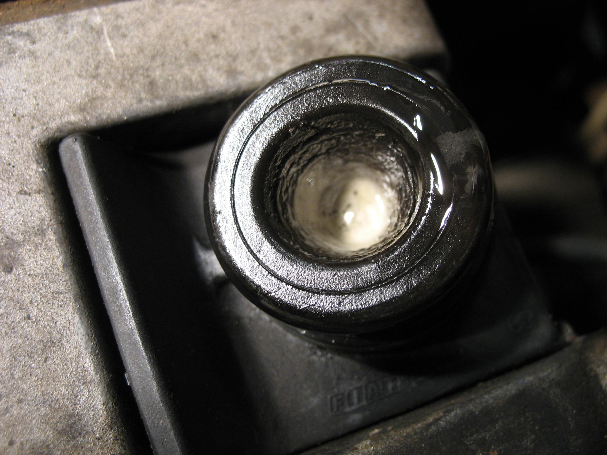
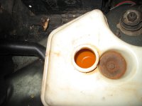
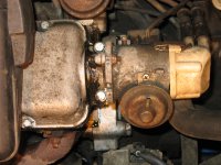
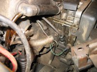
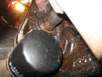
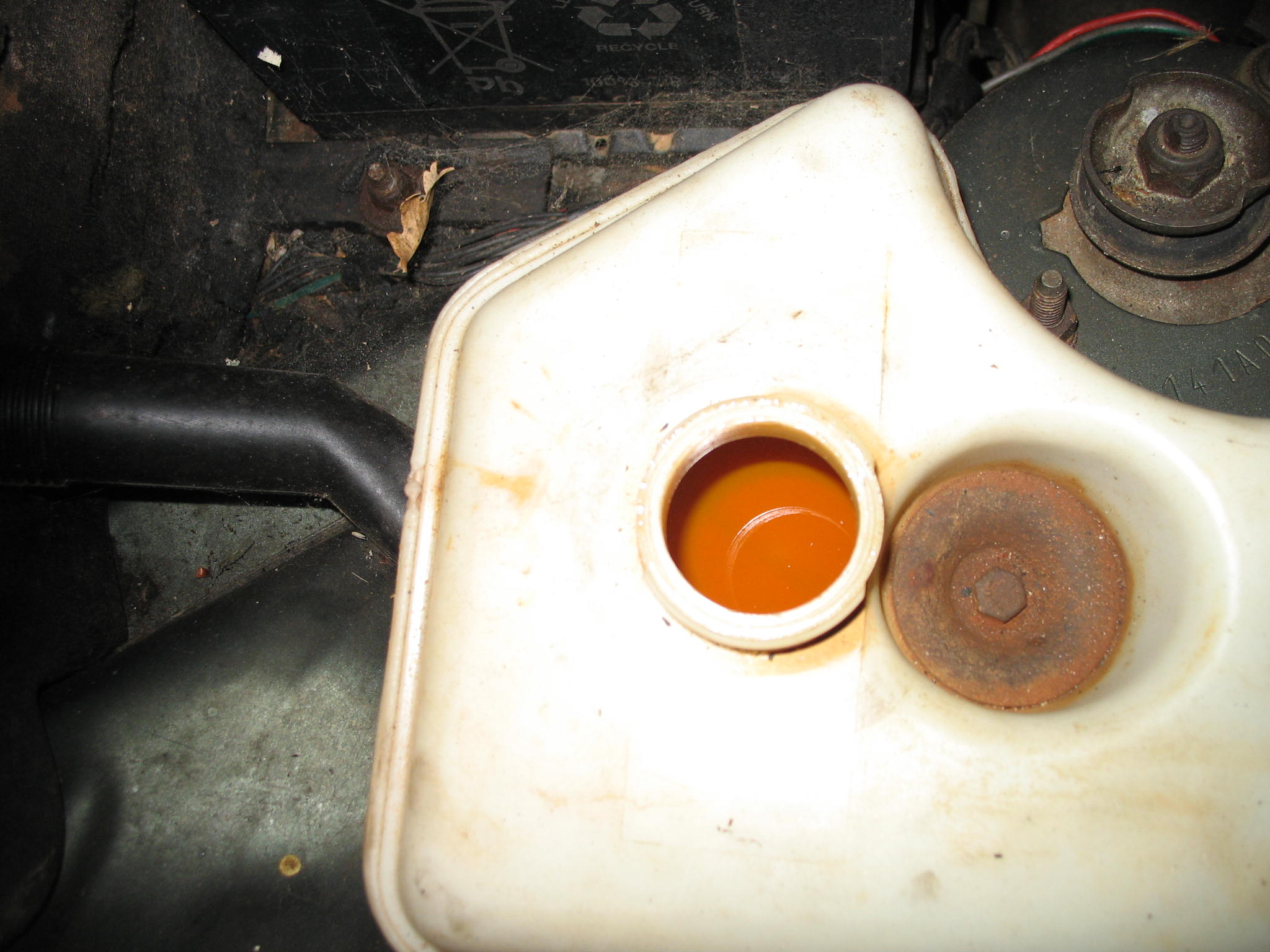
That is my bigger worry for now - bloody milky coolant and a bit of mayo under the oil cap.
IMG_18771.JPG

IMG_18843.JPG


How can I confirm my head gasket theory not having coolant presure test kit???
@CLS - your not the only one - aparently it is bloody hard to buy cheepo 4x4 without blown thru head gasket.

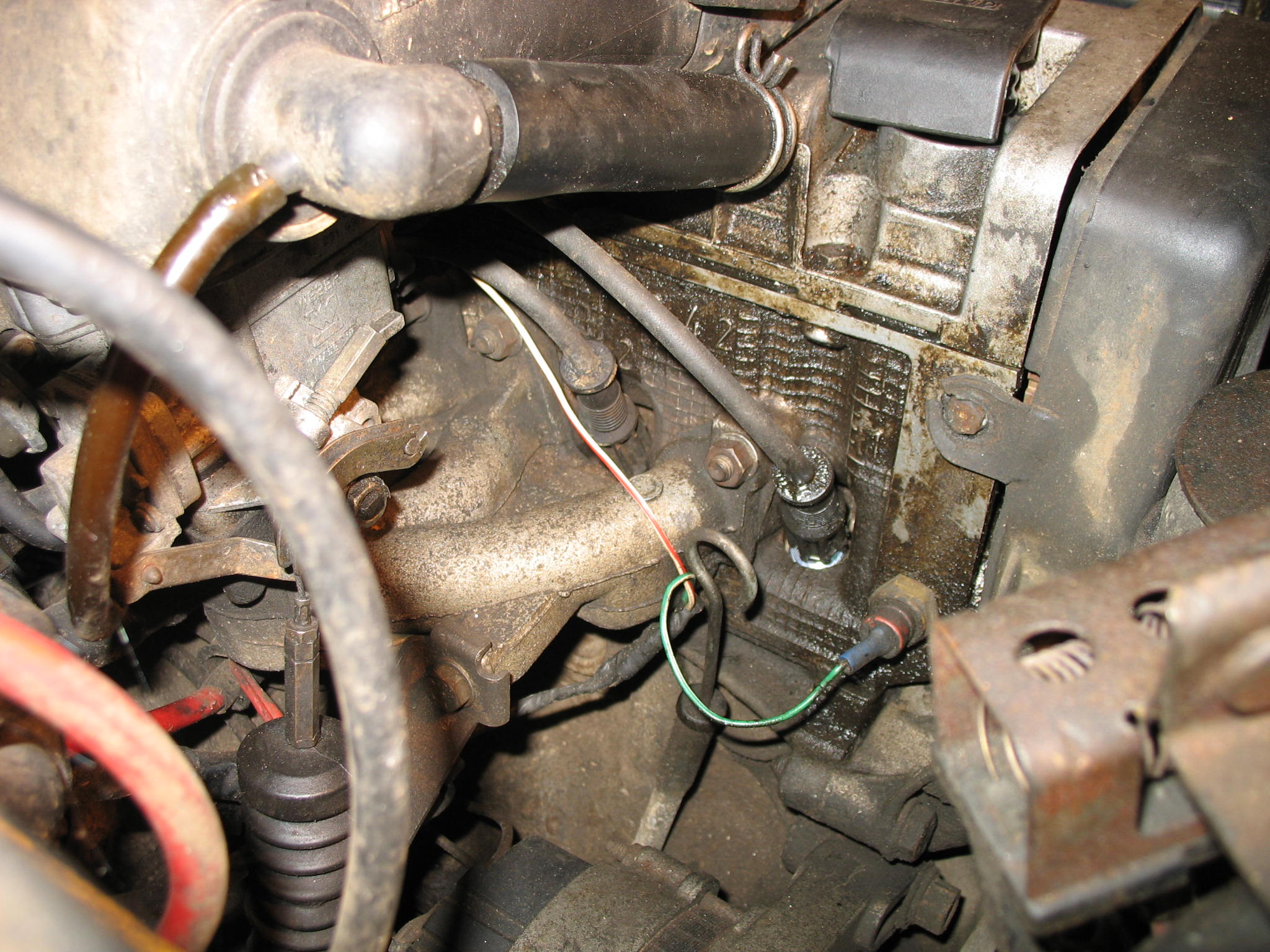
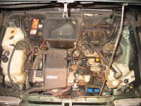
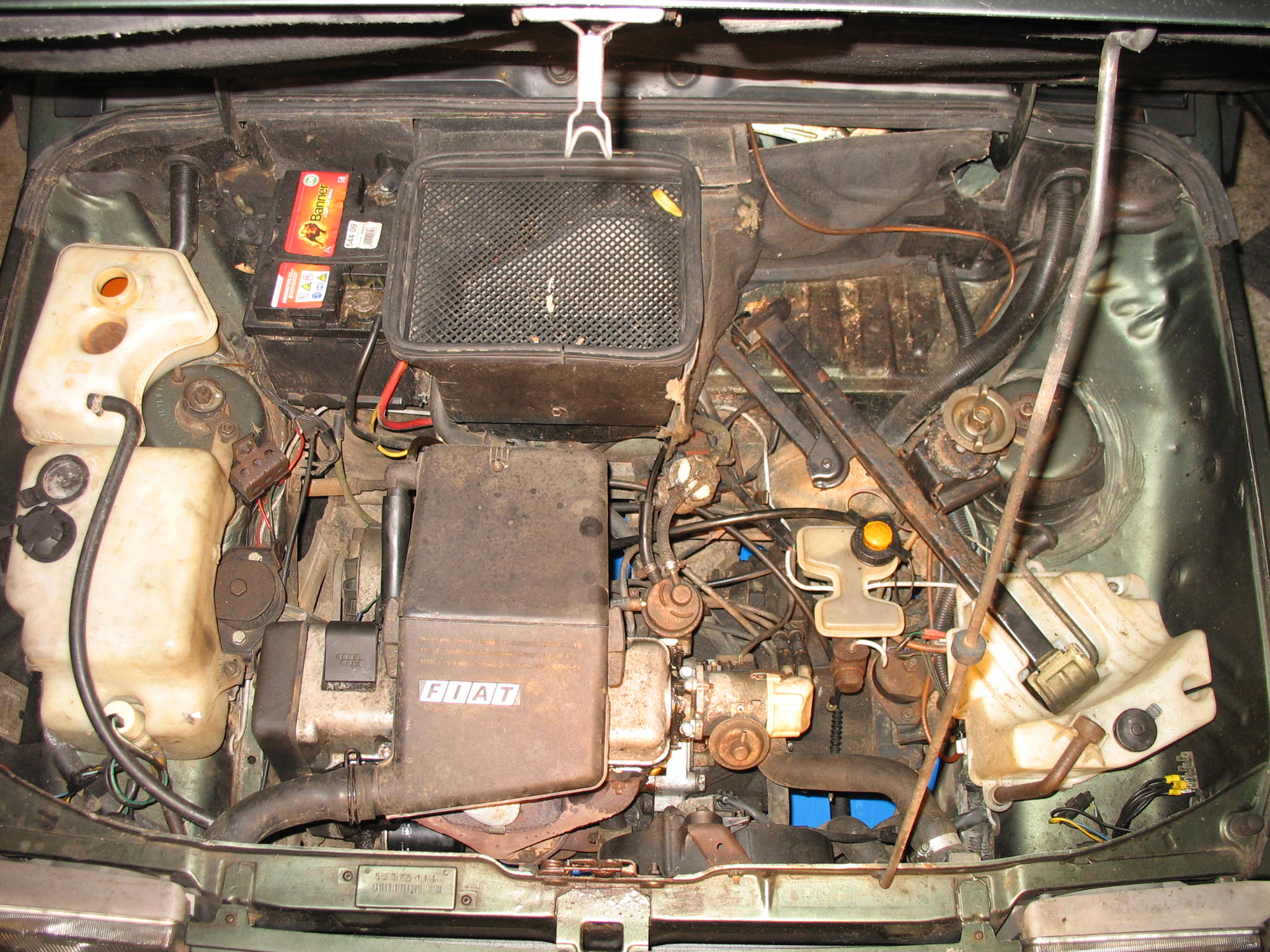
The rest of the engine bay seems to be fine,
IMG_18791.JPG


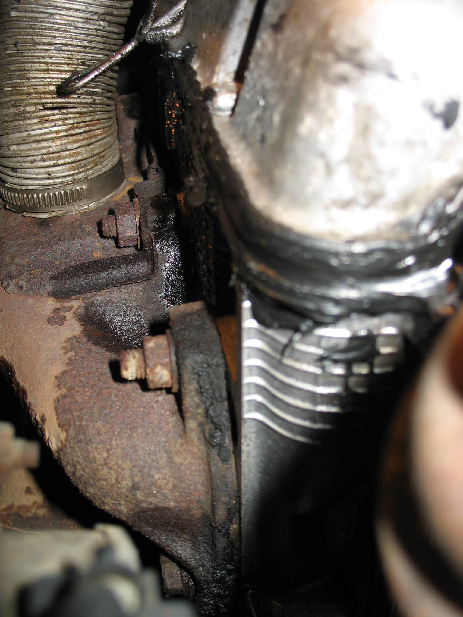
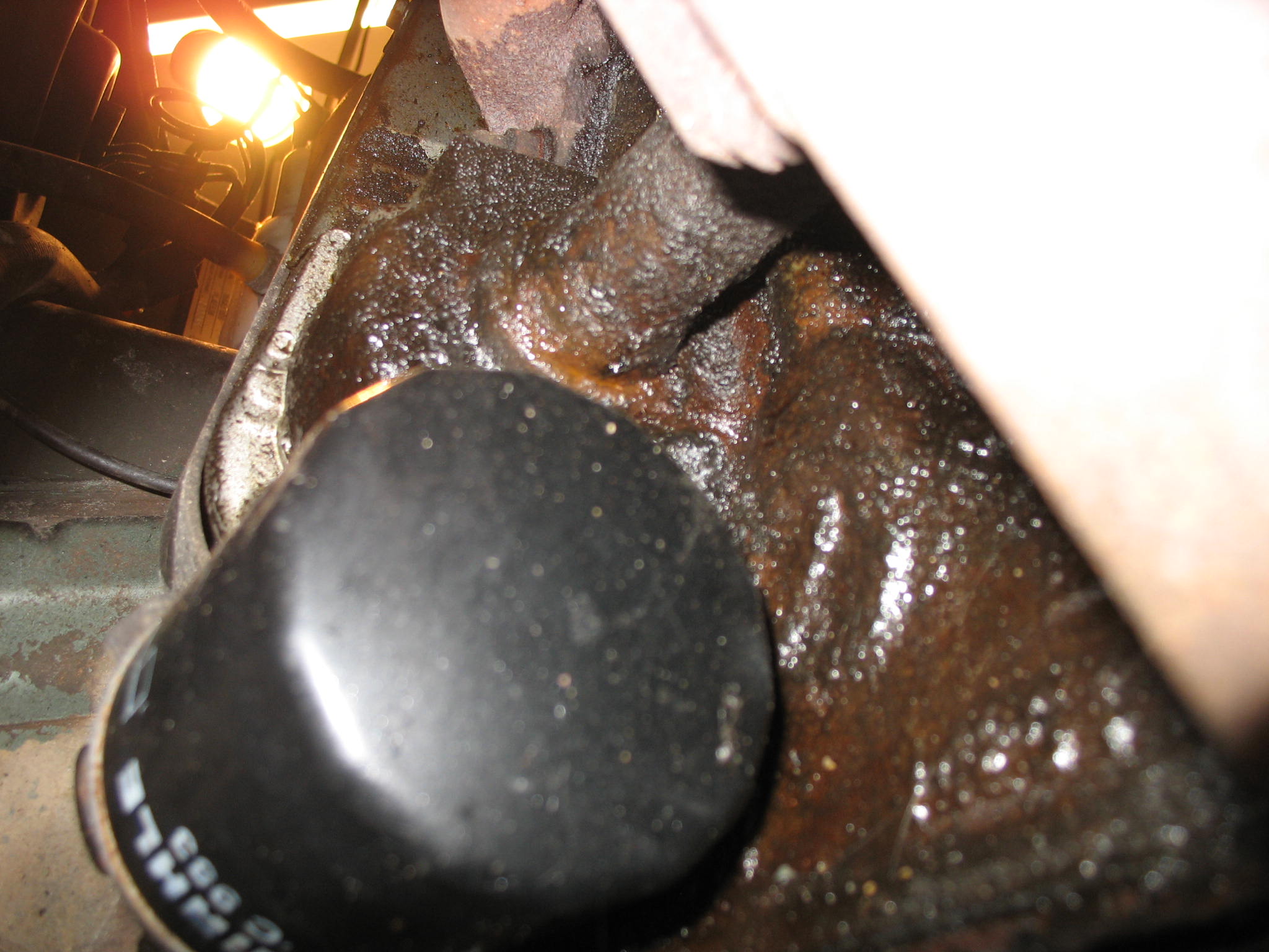
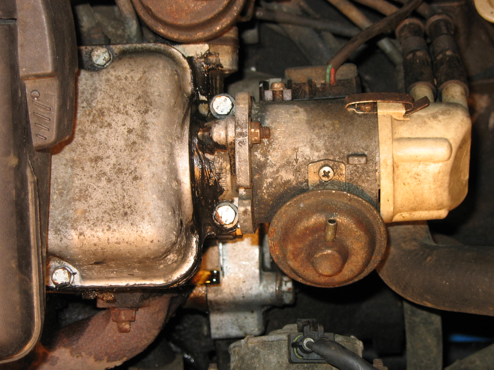
Did somebody in here mentioned a black silicone gunk as a fast repair?
IMG_1878.JPG


IMG_19241.JPG


IMG_18862.JPG


IMG_18821.JPG


IMG_19311.JPG


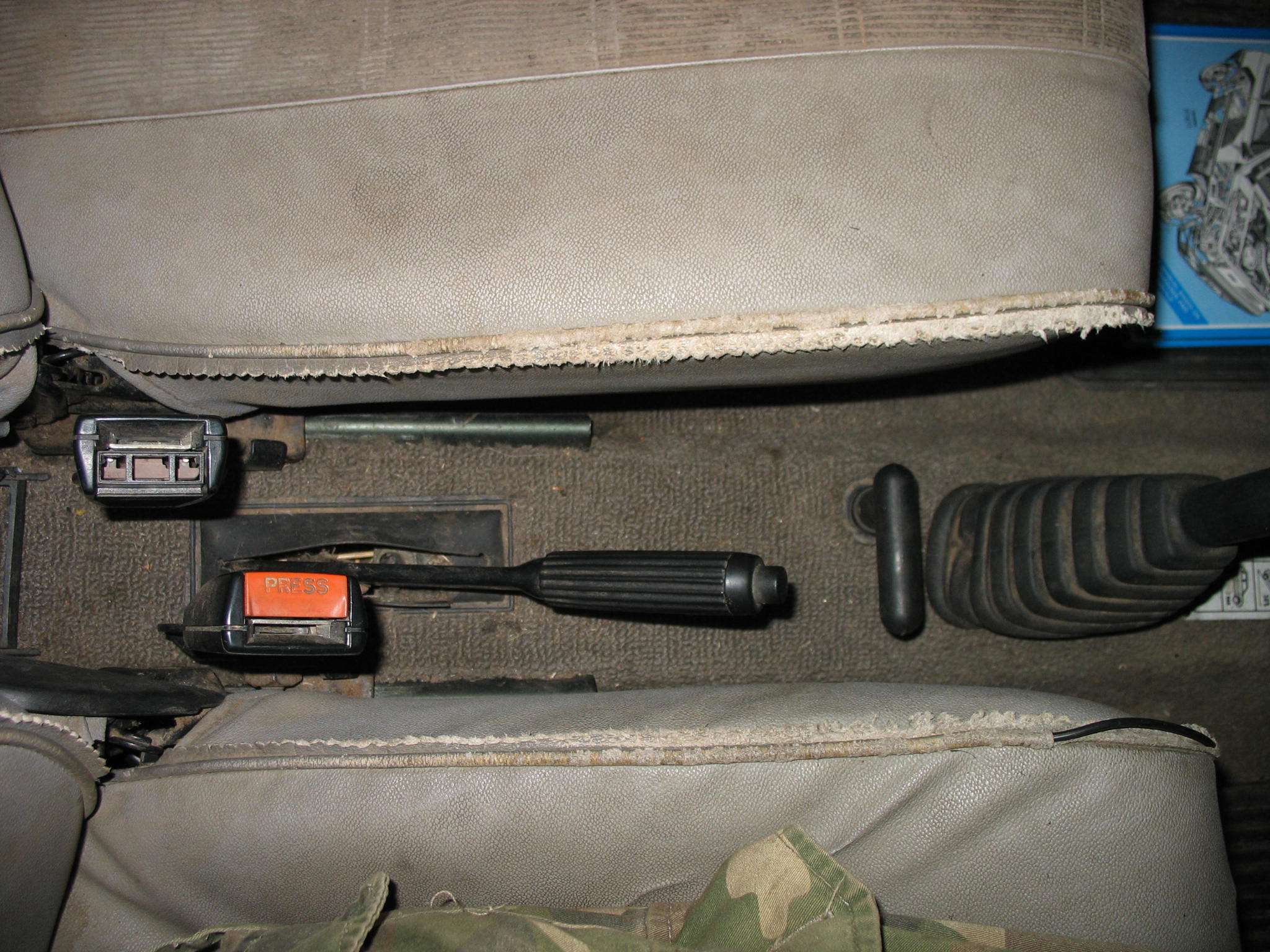
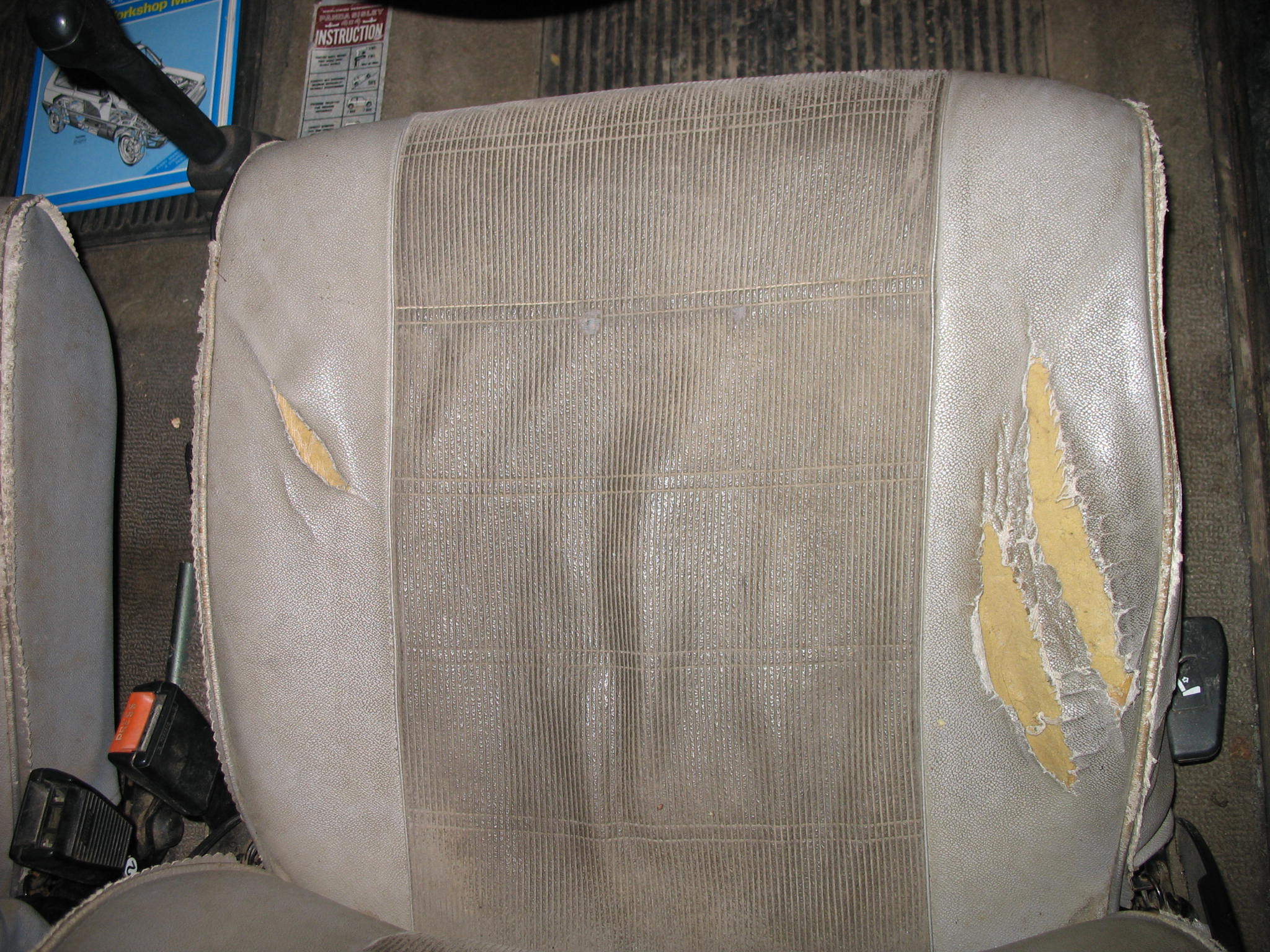
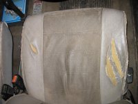
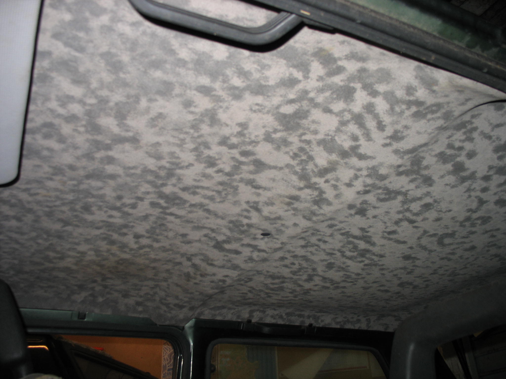
Interior as you can expect from car been used on a farm
IMG_19102.JPG


IMG_18901.JPG


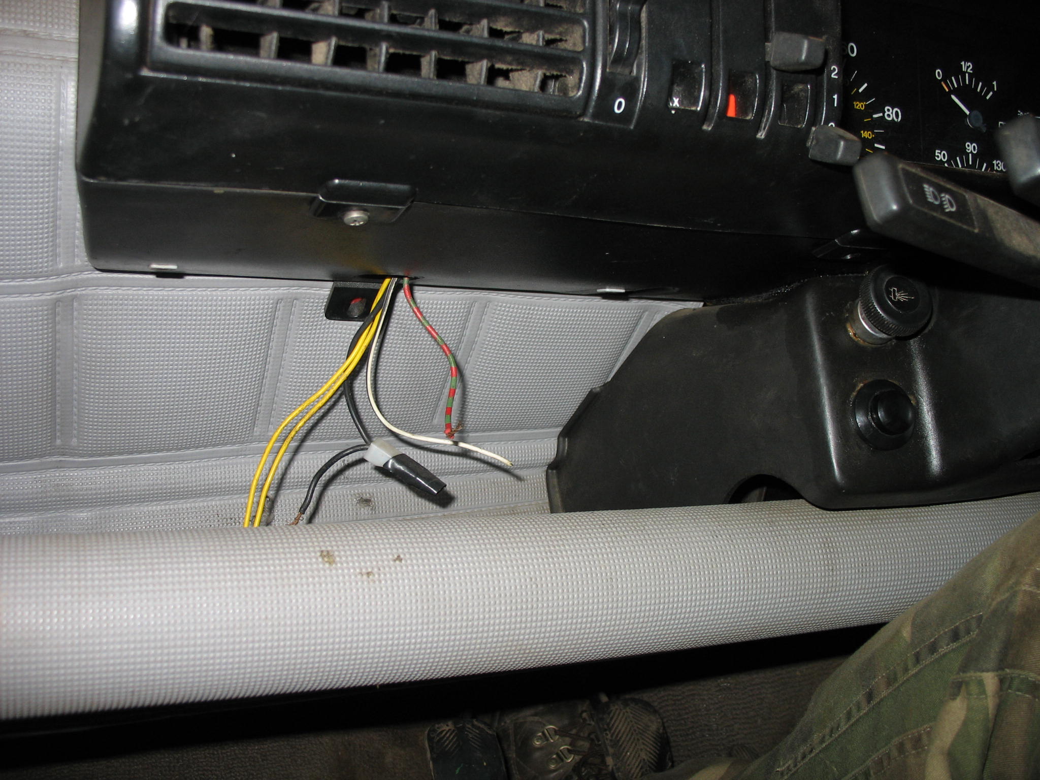
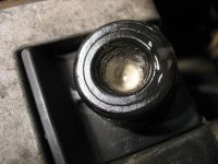
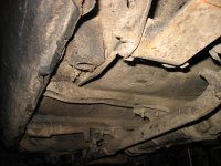
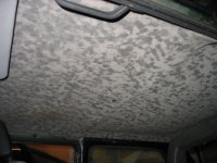
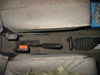
IMG_1874.JPG


IMG_19373.JPG


IMG_19364.JPG


IMG_19384.JPG


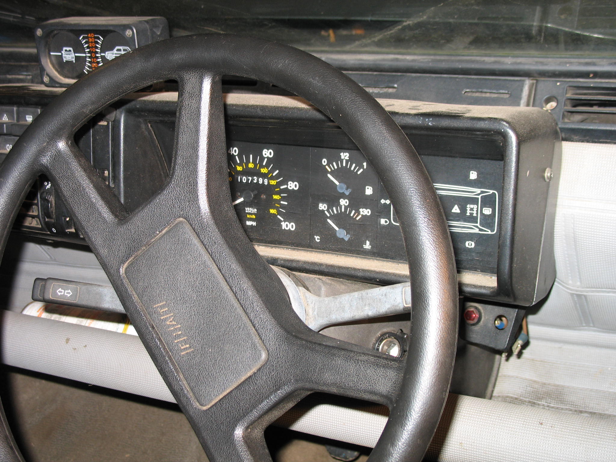
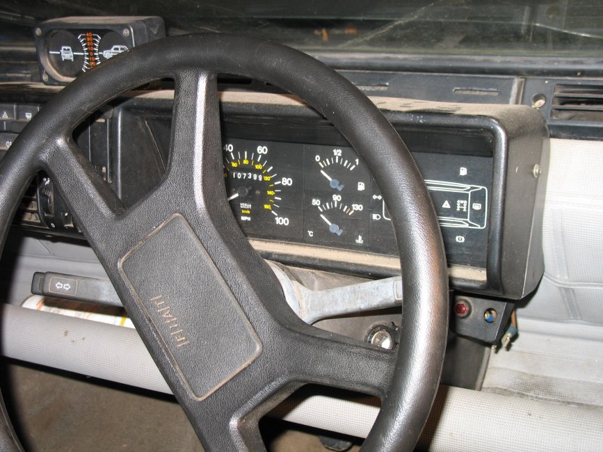
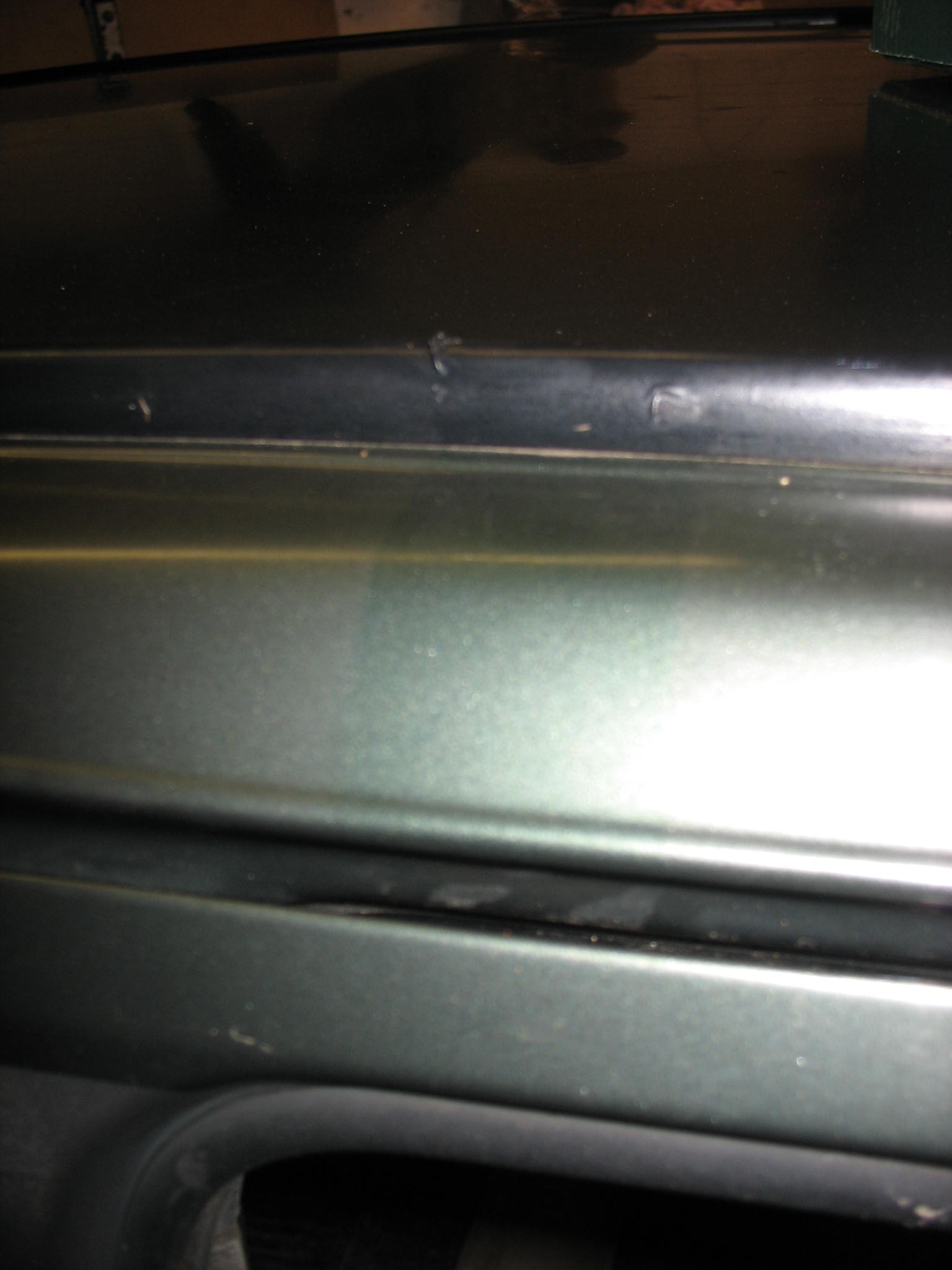
Not the geniune steering wheel and speedo, which does not make much difference to me at all. Roofrack presence evidence
IMG_18931.JPG


IMG_19081.JPG


IMG_1915.JPG


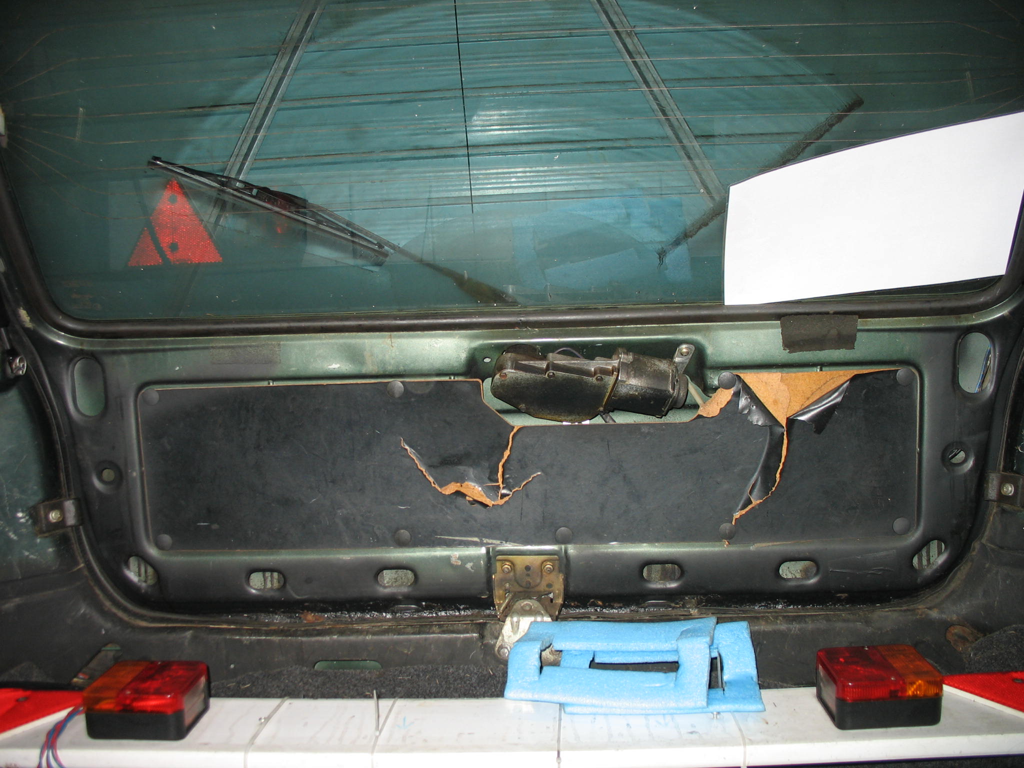
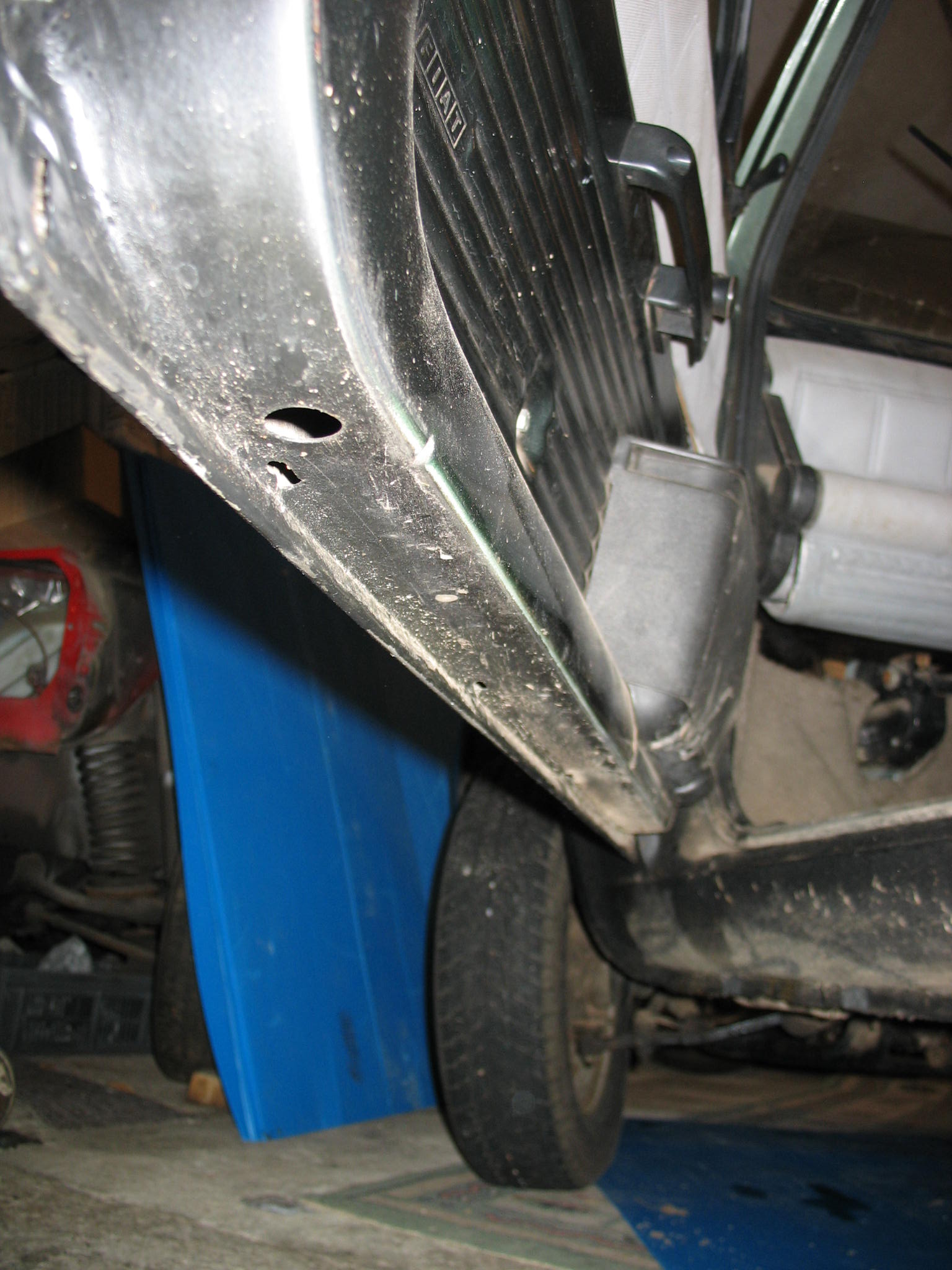
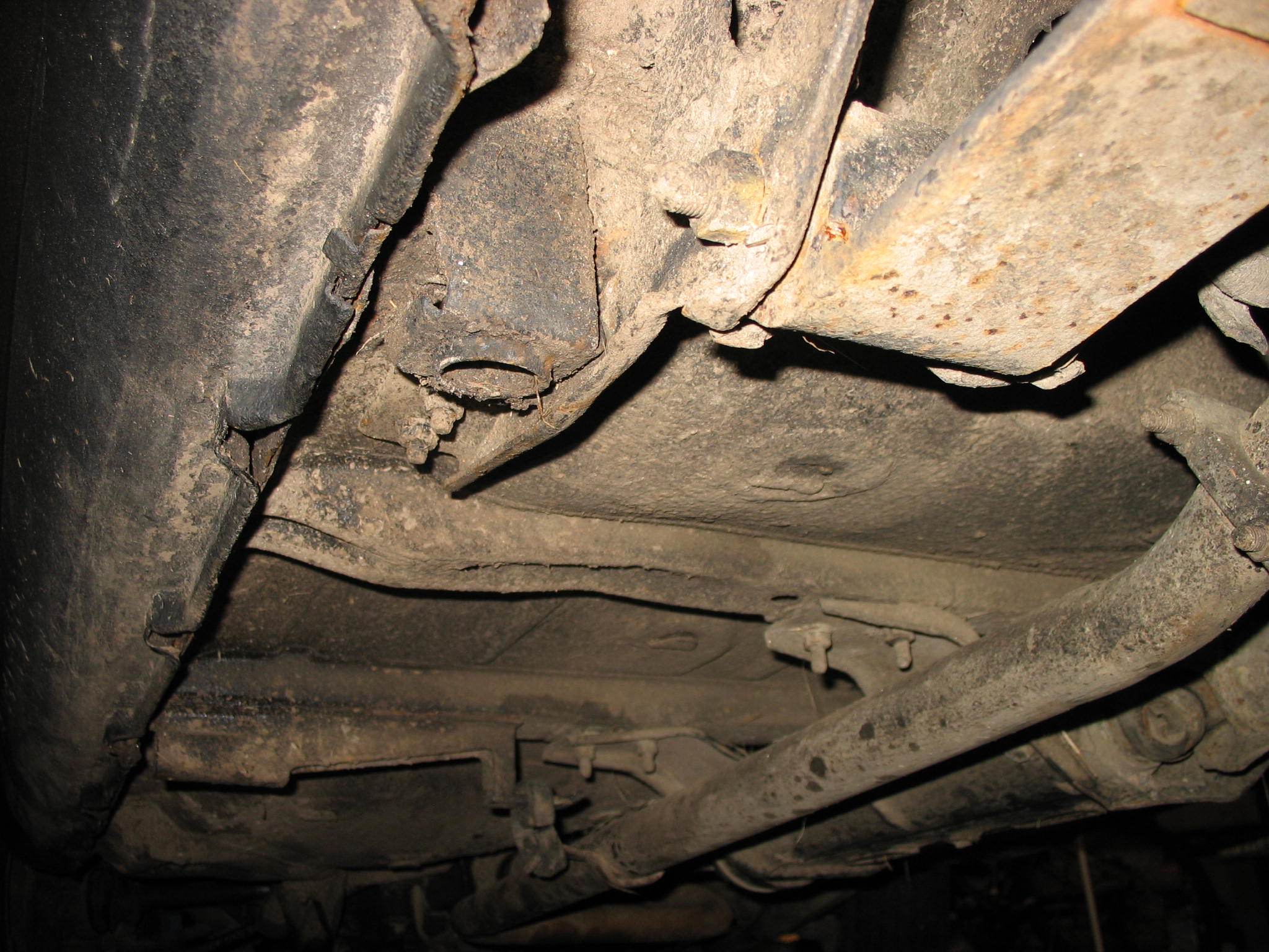
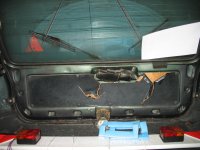
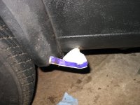
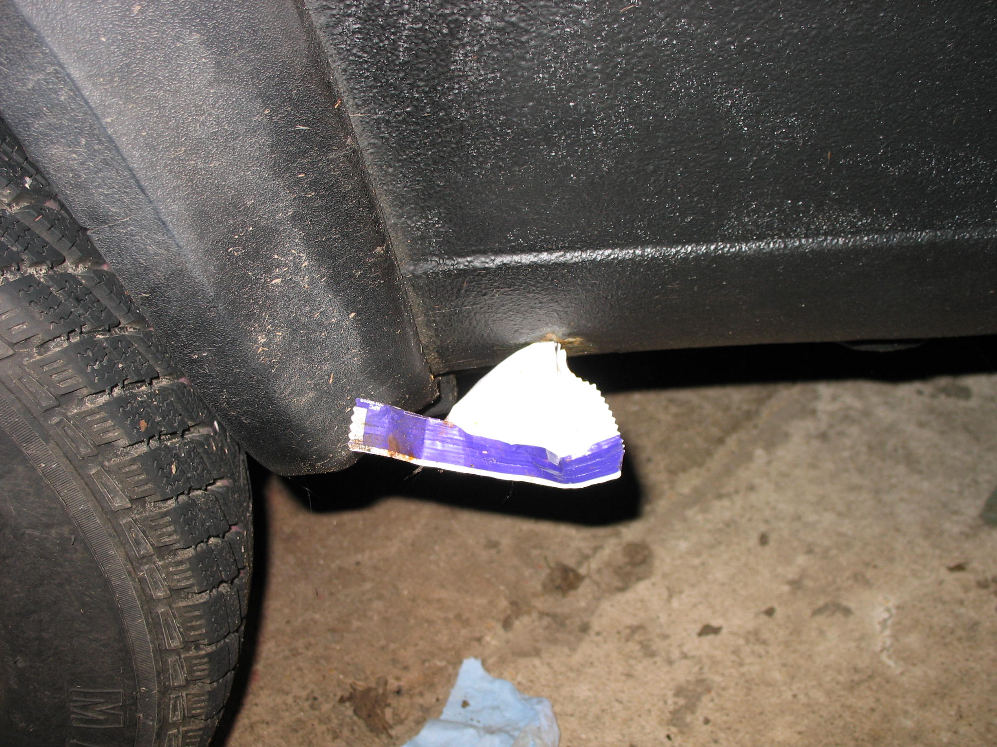
I dont want to know how this happened.
IMG_19191.JPG


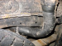
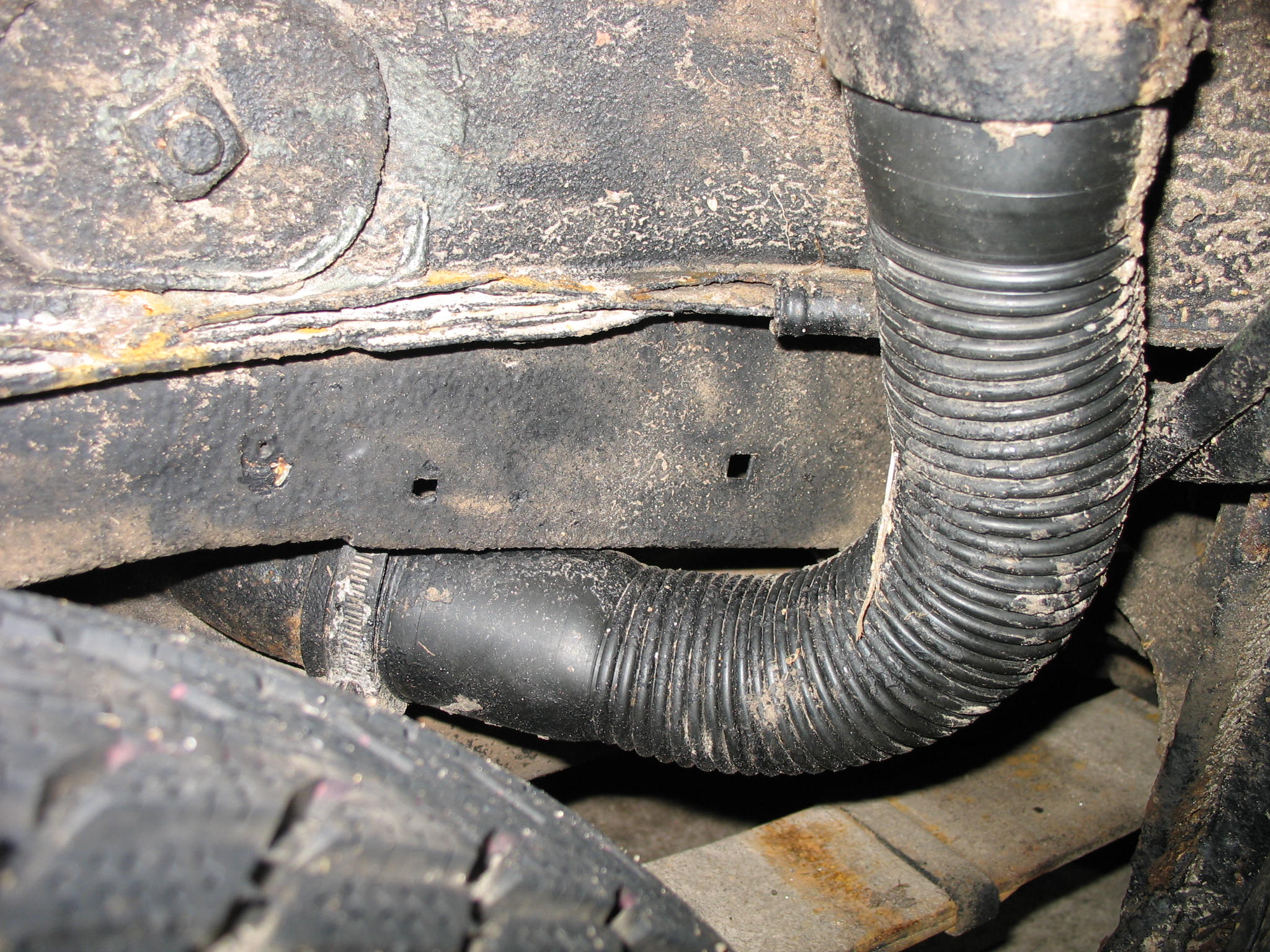
Filler pipe still untouched, what sort of DIY protections do you recon?
IMG_19202.JPG


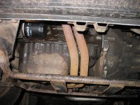
And time for the bad boy
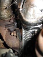
IMG_1946.JPG


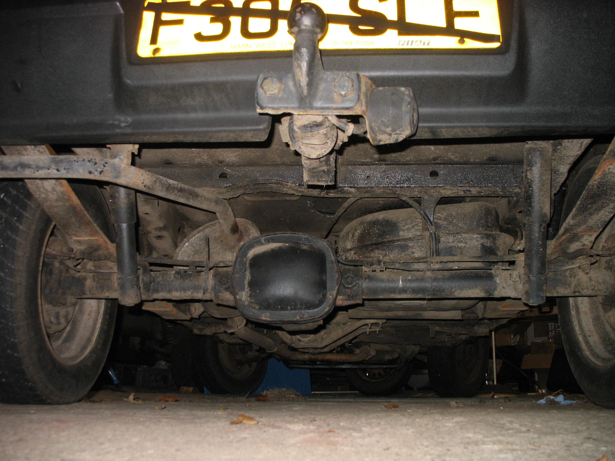
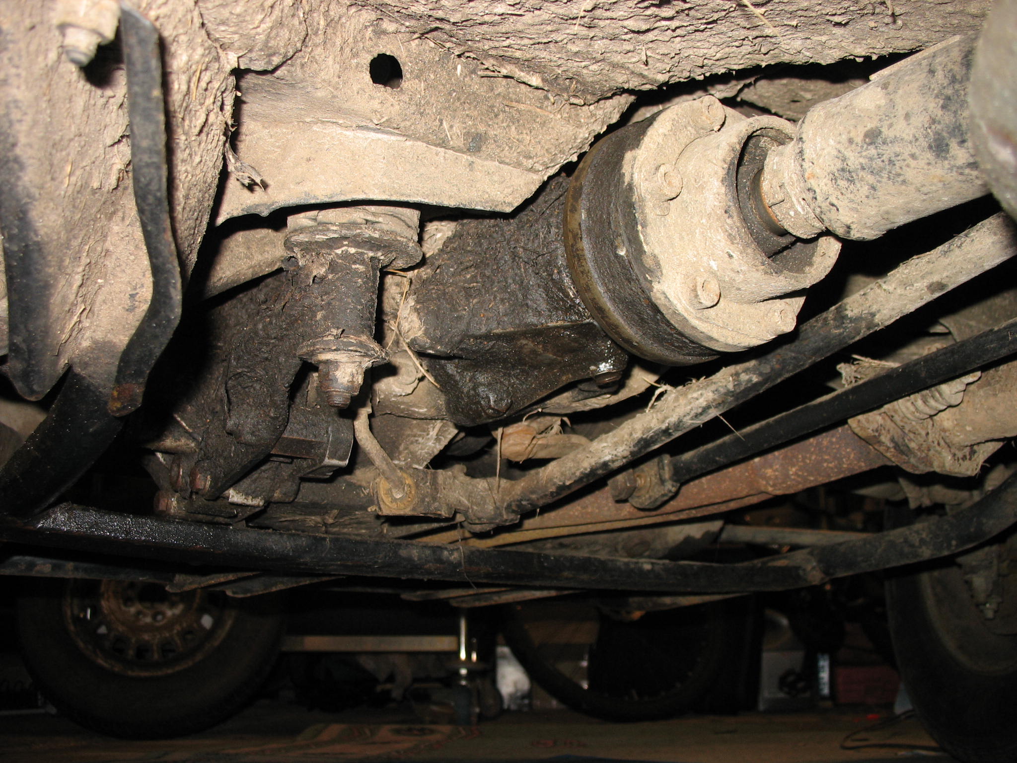
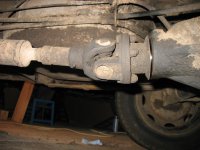
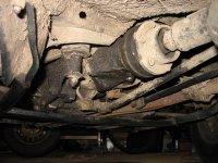
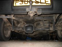
Is that gap between the propshaft and diff is normall?
IMG_19042.JPG


IMG_19022.JPG


IMG_19061.JPG


IMG_19442.JPG


IMG_19353.JPG


Dear FFCP section members, any comments, suggestions and observation are more than welcome, especcialy regards the 4x4 drive train i.e. leaks etc.
As above this might be the cool print of the issue.


IMG_36203.JPG


It did rotate freely when manually spun at the assembly stage, but in theory at certain rpm and frequency it can wobble more as the tripod bearing races are at stepper angle.
I'll get the front on stands and check from underneath at different rpm with suspension fully down and compressed a bit. If there will be noticeable difference outer cv joint to hub spacer will be thickened.
 
Last edited:
Done some literature study, findings are as follow:


Tripod joint


[FONT=Cambria,Cambria][FONT=Cambria,Cambria]The first occasion that the Tripod joints is known to have been used, in its current design, was in early 1960s. [/FONT][/FONT]
[FONT=Cambria,Cambria]

[FONT=Cambria,Cambria]The advantages of this joint are mainly the ability of transferring constant velocity and the low amount of axial force required for end movement. This joint can accommodate for axial displacement. This type of joint is also referred to as a plunging joint. Due to a lower amount of friction, for the tripod joint than other types of joints, a cooler operating temperature is maintained. [/FONT]


[/FONT][FONT=Cambria,Cambria][/FONT]


[FONT=Cambria,Cambria][/FONT]
[FONT=Cambria,Cambria]
[FONT=Cambria,Cambria]The Tripod joint has one major disadvantage hindering it from being used in applications with relatively high rotational speeds and large angles. This is due to the fact that the center of the spider plane moves around the center of the joint in a circular motion for articulated angles larger than zero. For each revolution of the joint this center completes three rotational laps [2]. This orbiting motion produces an inertia effect that increases in magnitude with the size of the outer housing. [/FONT]
[FONT=Cambria,Cambria]"[/FONT]
[FONT=Cambria,Cambria]will look more in to potential dampening methods.[/FONT]


A typical Tripod joint has up to 50 mm of plunge travel, and 26 degrees of angular articulation.
[/FONT]
[FONT=Cambria,Cambria][/FONT]
 
Last edited:
And this leads me to the later design of tripod spider ( less roller bearing ) where the races are allowed for bigger range of movement, therefore orbital motion of races would be lower or zero. Low chances of finding correct size , can take long time.

http://www.freel2.com/gallery/albums/userpics/16617/normal_IMG_0807.JPG


The wobble is build in to the design, but as the shaft angle increase it goes wild.
If it is 26 degrees full angle so it gives 13 degrees in one direction only.
Looks like during the acceleration n/s shaft breaks the 13* line.


[ame]https://youtu.be/-RMxVcq-RhQ[/ame]
 
Last edited:
Next things to watch is as Suggested by AndyH. during acceleration the camber change badly and as an effect the outer cv joint axis isn't parallel with the diff axis.
Shaft vibrations are "neutralized" if outer cv to shaft angle is the same )or close to) the angle of shaft to front diff axis. The torque pulses (chunky tyre = poor grip) created get worse with angle, rpm, and inertia.


So in my case camber was set to -2.42* with 2mm magic camber bolts, I'll swap them to 3mm bolts and change get the camber adjusted.


Another quote from technical literature:


"The shudder is generally understood to be caused when the general axial force (GAF) on the plunging-type joint simulates a horizontal vibration of the chassis when the vechicle abruptly accelerates. These problems are mostly releated to the internal contact friction forces of the joints translated into a cyclic axial force along shaft's axis. The amplitude and frquency of the general axial force and plunging resistance force may directly influence the vehicle's noise, vibration and harshness characteristic degradation."


Bloody long list of things to check and hi-science behind simple suspension lift, but we will get there in the end.
 
Last edited:
But like it says in your quotes Jacob, it's clearly being amplified by the fact that it's a crude, primitive engine with only few mounting points, of which are probably as old as the car. This will make it seem worse, as stated. I recon it won't be helping having a bigger or more weighty wheel either.

I've never had any kind of vibration like this in mine during driving/accelerating. I've heard the "clicking" noise in full articulation before as Freddy had stated earlier, but it's never presented a problem.

It's where to stop with these investigations, and when to enjoy the car for a bit!
 
The Engine mounts on mine are also brand new so it could be perhaps down to mounts if they haven't been changed.


Both top ones were renewed less that 5k mile ago to OE ones, lower one was change to used but good condition.


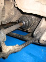
Base on simple angular analyse done on the photo below showing full down articulation the shaft to diff flange is close to 15-16 degrees.


IMG_36252.JPG


With passenger inside the vibrations on acceleration are much much lighter, so I presume with bull bar on and 15kg winch at the front the extra weight should reduce the 'nose up' effect.
Next small factor adding to the rest probably is the fact that the rear end had a bit less lift making the body more levelled up which as results will give stronger 'nose lifting effect'.


I've got short check list to follow.
 
Great thinking and research. For what it's worth, I like the theory about rake - front to rear ride height making a difference to this phenomenon.

-I think I notice a difference accelerating hard up hill compared with down hill. Anyone else?

Back to your question on the shims - I've followed the instructions in the 4x4 manual on measuring and adjusting the stack but its difficult to feel or hear any differences. On the different flange/gearbox combinations I've put together (they've all leaked oil, so don't consider me an expert) the stack height has varied and I've altered the pre-load but not reached any conclusions so just stick to what the book says.

Still want to see a gearbox that has failed to understand where the weaknesses are.

Great work J.
 
Back to your question on the shims
fiat used shims from 0.6mm to 1.35mm every 0.05mm so 16 different shims warying every 0.05mm for the short shaft flange and from 0.4 to 1.0mm, so 7 warying every 0.1mm for the long one side bearing. It really gives multiple combinations, so it can be different in every 4x4 box on this forum:)

I had almost zero camber on my trekking about minus 0.1-0.2 degree, -0.12 on one wheel and -0.18 on the other, small negative camber, steering/cornering greatly improved at the cost of bigger force on the steering wheel, but perfectly acceptable with 175/65-14 wheels unless you are small korean girl :) .Max tested lift on my car was +45mm, without anything similar to wobbling engnie ,or shaft/shafts.
 
Last edited:
I think I notice a difference accelerating hard up hill compared with down hill. Anyone else?
.

Same here, it was noticable on the lift kit rev.1as well.I did put that agains new off-set flange and not altering the shims. As the theory was that driving up the hill gives more load on to the box / diff bearings therefore the noise/ light juddering - but tnow we know that it was too step angle of short shaft due to nose lift effect.

I've measured the angle of the short shalf with wheels onthe ground, the angle value between g/box and shaft was 12,47 degree surely during the acceleration the angle was increasing and way over the maximum 13 degrees where plunge joint can operate correctly.

New approch was taken, spare wheel, jack back under the bonet, bullbar on and the shaft angle dropped by nearly 2* already. Gone for short spin - difference is noticible streight away. Some juddering still noticible when accelerating up the hill.

Lesson lern - maximum angle of short shaft is 13*.
With winch fitted car shoud be completely cured.
 
Last edited:
think i remember Tibor having this issue with his panda offroad. the only way he fixed it was by lowering the engine and gearbox :/


is there not a way you can extend the axles by using the uno ones? if they stick out more than angle would be less?

The engine/transmission/lower arm mounting point drop is actually making the tyre to wheel arch gap bigger, correct way if 14" wheels and massive tyres will be fitted ( 1242cc first) in any other case sort of false thinking as the actual clearance between the engine and ground remain exactly same. On my current rev.2 setup there is 24cm clearance as well. Therefore you got all the welding to the lower arm/ body mounting and all the spacers fabrication vs. light judder under heavy acceleration.


The Uno shafts are currently 8-10mm to long, they fit fine but with the wheels still in air the tripod end was bottoming out inside the cup/tulip/ diff, even with the thinner outer cv joint spacer. Custom made/ extended lower arm and tie rod are necessary (planned for rev.3 which will focus not of lift but suspension travel)


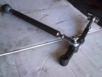
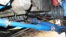
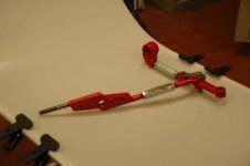
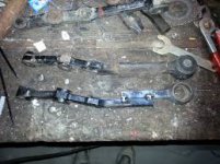
The bottom right example/ modification is not recommended from obvious safety reasons.
 

Attachments

  • 20118302384__2.jpg
    20118302384__2.jpg
    31.7 KB · Views: 43
  • 201227175916_4104.jpg
    201227175916_4104.jpg
    38.2 KB · Views: 46
  • imagesCAG9JFUE.jpg
    imagesCAG9JFUE.jpg
    4.2 KB · Views: 50
  • imagesCALIBV90.jpg
    imagesCALIBV90.jpg
    10.7 KB · Views: 51
Last edited:
I am lowering the whole eng/transm. on all 3 mounts by 1cm. It 'll help a bit the short driveshaft/angle problem ,values greater than 1cm also possible

1612879000_1438122859.jpg
 
on all 3 mounts by 1cm. It 'll help a bit the short driveshaft/angle problem ,values greater than 1cm also possible


Definitely will help, I'll look into what spacers/washer I've got available and the clearance between sump guard, even 5mm is better then none!


I'm just reluctant to alter/mod the lower arm mounting point as it does take some abuse.
 
Say hello to my new design.
15mm handbrake cable spacer, can make more if someone is interested.

Black Nylon 66 block machined and drilled out to fit over the cable rest plate.
Rest plate is sandwitched between, block is help in place by M8 bolt which goes through the centre hole not used on 4x4 only on 2wd.

IMG_3668.JPG


IMG_36721.JPG


IMG_3671.JPG


Initially i've made those u shape spacers, will see what slack in cable will be after some time in use, spacers will be probably removed.
Photo with wheels on ground.
IMG_3673.JPG


Photo with free hanging axle, no strain on the cable at all.
IMG_36741.JPG
 
Kolza.
I am intrigued, How do you know it is nylon 66?
I have worked in plastics for 40 years and most numpties just assume plastic is plastic and there are no different varieties.
Enlighten me.
Not suggesting in any way you are a numpty.
Dave
 
I am intrigued, How do you know it is nylon 66?


Good question Dave, but in this case I actually know what was on purchase order, therefore it is nylon 66 in black ( nice oily touch ) and probably I would not use non 66 grade for this and any other automotive application.
 
Last edited:
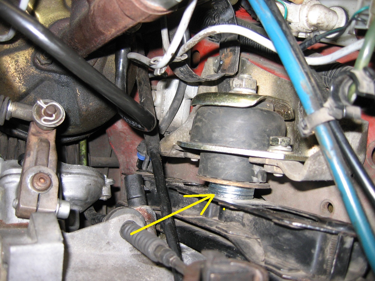
After closer look at the gearbox side top mount I can say that the large metal washer between metal bracket and bottom of the rubber mount is missing. in this case the engine was out of level adding up to the short shaft angle.
 
Back
Top