post 7
The connection is for a Panda OEM towbar electrical connections
wrong it the parking sensor, same colour wires, same type of connector
In a closed circuit (bulb of 12v4w standard, the resistance on power on, 41 ohm raising to 410 ohm).
wrong its a 12V21W bulb we are talking about
Post 9
Due to this, if one changes the load or resistance of the circuit, the voltage at the transistor can jump to much higher than what it is rated for - as a result, the transitor will short / overload on use / time bulb blows. Since this transistor is one of a few in an IC, the IC blows and the 'Body Computer' fails.
wrong the BSI detects the current and switches the output off
Not that the replacement body computer is expensive,
wrong the BSI is very expensive if you factor in replacement cost and reprogramming
its actual location is bolted to the inside of the firewall behind the steering column and console. As a result, to replace it (not that I have) requires removing the complete dash to get to it.
wrong you don't have to remove the dash
Disconnect the battery negative, remove the fuse box cover, Undo the retaining bolts, Disconnect all the, connections.
What I suggest is that you, with a multi-meter, (set to 20v DC, one lead to chassis, other to the tags) figure out the correct wire on the aforementioned multiplug for reverse, and either use that, or add a toebar intermediatary box to trigger the reverse.
hang on a minuet we are using a multi-meter
It is never a good idea to cut into OEM car wiring.
Right but sometimes unavoidable
post 13
10,000,000 ohms is 10M ohm... and that will make a huge difference
wrong simple ohms law
Adding a 10M ohm load, as you suggested, will fry the control circuits in the body computer. Understanding loads and resistance should tell you that the lower the current between trigger/switched circuit and ground, the higher the resistance and the further one is from the limits of the components within the body computer. Semicondutors do not handle over current or overvoltage and will blow. Yes, the fuse will blow also, but that is the least of your problems
wrong adding a 10m ohm resistance in parallel to a 7 ohm bulb is still 7 ohms the difference is infinitesimally small
On this very forum, there are posts about overloaded cables and melted plastic at the connectors. Fiat, like every other car maker, are at the whims of accountants who reduce cable thickness to the absolute minimum to reduce costs in manufacture. This causes a problem, especially in a DC circuit when an extra load is placed on a cable due to arcing contacts of a corroded connector / or a bad earth. As a result, the cable heats and either trips the saftey circuits (if it is directly controlled by the body computer) OR if it is via a relay, can melt connectors.
wrong the cables capable of carrying easy 3x the load, not that the camera adds any significant load
To avoid potential problems, if you must connect to an OEM wiring, disconnect the battery and leave for at lease 2 hours
wrong long gone are the days of everything stored in volatile memory and kept with large capacitors, the only thing kept this way is the RTC with no back up, which makes me wounder if you have even seen inside the BSI
post 17
You are correct in that a .5mm cable can handle 12-15v, 21W / 1.4 amp with ease as it is rated for 7amp, however, when a DC (car battery / suply) contact arcs as in a dirty connection or where cables are twisted together, the current jumps by a factor of 10. Therefore, the 7 amp cable is then needing to handle 14 amp not 1.4 amp. Even perfectly twisted cable connection will arc in a car due to the vibrations induced by the engine / suspension.
wrong a properly secured cable with a soldered joint should never arc or break,
Probing the car with a standard multiimeter / test light similar to the previous postee to check for a voltage etc. is beyond insane as if you short a canbus signal (and there are usually 4-6 of them in most cable looms) cable via the bulb / meter, you WILL blow the canbus chip / a canbus reader/decoder chip in another CANBUS device EVEN if the car is powered off. CANBUS is a TTL / digital signal, and most cars have two of them, a low speed and a high speed circuit.
Wrong probing with a multi-meter is exactly what you suggested doing in suggested doing in post 9 "What I suggest is that you, with a multi-meter,"
Wrong there is no CANBUS in the rear wiring loom
Wrong shorting the CANBUS will not kill anything, it will stop communication and you may have to clear the codes
there's no CANBUS in the rear loom
Now, I'd like to see if the previous postee can get 4-6 years of 3rd level degree information on the internet? My qualifications and experinece include over 40 years working with electronics and digital circuitry. It seems to me that said person does not even understand the basics of Ohms law!
I am starting to doubt this 40 years working with electronics and digital circuitry
post 19
First disconnect battery and leave it for 2 hours minimum. Good idea is to remove the battery and leave it for a day. You do not want any of the canbus system to retain any charge
Wrong there is no CANBUS in the rear hatch
Two hour, a day why theirs nothing to retain a charge, 2 minutes is recommended by Fiat on the airbags and that's being cautious
Now, for the cables, there will at least be 1 cable being exposed and shorting to the chassis plane and Murphys law it is one of the CANBUS low speed cables which is being grounded. That equates in the canbus signals being shorted and devices that require to 'know' when another device is operating / finished fail.
Wrong there's no CANBUS
CANBUS system is a smart design and since most devices are on CANBUS Low or High, adding functionality / display on any device is relatively easy as compared to the old individual device wiring. It also links all devices to each other. The airbag ECU is connected to CANBUS low, like wipers, rear demister etc, so there is a connection between the cables at the aforementioned grommet and the airbag.
Wrong wipers, rear demister aren't on the CANBUS
post 27
In relation to parking/reverse sensors, I have not come across a Fiat Panda with that design of rear bumper that has either mould marks and/or the plastic clips on the rear of the plastic bumper for parking / reverse sensors, so I doubt that that connection is for parking/reverse sensors. Secondly, that plug has a removable cap on it to stop water / dirt ingress. Normally, in a car model, the facilities are installed to allow a garage to add the optional extra like parking / reverse sensors without having to replace such a large item like the colour coded bumper. Secondly, in a mass production, making something unique is avoided. So logically, parking/reverse sensor connection does not seem valid.
wrong it is the parking sensor
Post 29
Devices which may cause arcing include switches, circuit breakers, relay contacts, fuses and poor cable terminations.
Arcing can also occur when a low resistance channel (foreign object, conductive dust, moisture...) forms between places with different voltage.
If a circuit has enough current and voltage to sustain an arc formed outside of a switching device, the arc can cause damage to equipment such as melting of conductors, destruction of insulation, and fire. An arc flash describes an explosive electrical event that presents a hazard to people and equipment.
An electric arc has a non-linear relationship between current and voltage. Once the arc is established (either by progression from a glow discharge or by momentarily touching the electrodes then separating them), increased current results in a lower voltage between the arc terminals.
Wrong high current does not melt the connector, its the hot plasma 2,800 to 19,000 °C
post 32
Explain, using your logic, why car headlight bulbs blow when there is a poor connection on one or both of the battery connections as the arc would be created at the battery terminals, not the bulb the other end of the line?
No idea where this came from this nor the next question below has anything to do with anything or make any sense
One of the factors is said to be the a/c spike coming from an alternator, but that can't happen since it is rectified by the diodes / rectifiers on the rear of the alternator. Also, the alternator would not be creating voltage / current when the alternator inner coil is not energised by the battery during the time of partial / disconnection!
Wrong the coils remain energized as the alternator is spinning and still pumping out 14.1V
Post 34
C - I suggested adding a £20-£30 trailer box for a few reasons -
- It does not alter the load on original circuits to excede even the most sensitive run.
- It seperates the load of a device (camera) so if it fails, no damage to reverse circuits will occur.
- Options of secondary power socket can be added.
- No huge extra work is required to fit same, since the OP is already running a cable the length of the car.
- Toe bar is therefore mostly wired if the OP / another wishes to fit it at a later stage.
- Every toe-bar box comes with its wiring digram (i.e. what cable to connect to what)
- No real change is made to the OEM wiring of the car... and as such, no damage is possible to it.
extra time, expense, work, more load on the BSI
goes
against what you said in post 9
"It is never a good idea to cut into OEM car wiring."
also goes against as you are now adding a similar extra load to the indicator x2, lights,brake,fog
"Due to this, if one changes the load or resistance of the circuit, the voltage at the transistor can jump to much higher than what it is rated for - as a result, the transitor will short / overload on use / time bulb blows. Since this transistor is one of a few in an IC, the IC blows and the 'Body Computer' fails."
post 37
Another idiotic mistake.
In a car, the voltages are around 12v, but it is DC and has currents of 160 amps.... while in domestic, voltage may be higher but the current is a lot less. It is a common mistake of people who have little information to presume the lower voltage is safer!
@koalar is a typical example of a little knowledge may be dangerous / lethal.
Wrong, we are talking about the wiring in the rear, let use some common sense, and stop with the name calling, There nothing approaching 160A in the lights cluster, i am not working in a power station, electric vehicle, over head, power lines, or anywhere else, there is nothing here that will kill me or anyone else
wrong a car battery can provide a lot of current, the body can not draw this current, the low voltage and your body resistance limits the current
post 47
In simple terms, it is not the voltage (amount of units*) that can harm, it is the current (strength of each unit*). A domestic / comercial wiring is protected by at least 20 fuses / sensor circuit breakers in a circuit and limited to normally 40 amp range. A car battery will put out up to 200 amps at peak.... which can burn through human skin into the wiring in the body (nerves etc) and across the heart / brain (though for some of the people posting here, it might be years before that is noticed). The voltages / currents within the body are in the range of 1-2 micro volts and 1-2 milliamps. As a result, if the voltage/current raises in the body via an electric shock, each muscle contracts to such force to break bones and rip muscles from the bones. Even if you survived the shock, your bones would be burnt / in powder.
wrong and stupid, a battery can push out 200 or more amps across say a starter motor of less than an ohm, but your skin has very high resistance
post 54
The Haynes car manual identifies the colour of the wires on the rear cluster (18) for each bulb circuit. The reverse light (a) is powered by the white cable (Bianco) and the black (Nero) wire as ground connected to pin 3, but since the other end is connected to pin 1 connecter F directly to the body computer (7), it is still not advisable to directly connect this to an external device like a camera without at least sone interface / protection between them. After all, the camera will be outside the car and in the event of a rear end collision, could be squashed. This has the possibility to short the reverse signal to ground, and you would be left with no reverse lights, or even worse, half or more of the lights unable to work. This is not only dangerous, but illegal to drive the car that way.
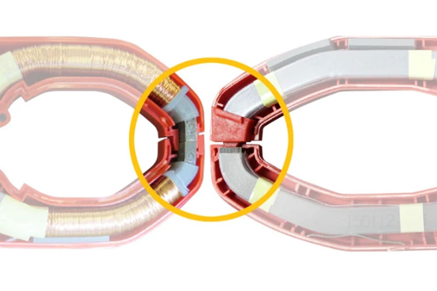
wrong, and unnecessary diagram already in post 10 correct colour wire was identified in post 1
post 58
A clamp meter measures AC current, not DC current so it will not work on a car to measure current. I presumed, foolish me, that you knew how to use a meter!
wrong, very useful they are to, put on the starter cable and watched on a scope you can see the 4 higher current as each piston get to top dead center, and if synced to an injector pulse you can work out which cylinders aren't making compression, without taking the spark plugs out to do a compression test
As a result, water will eventually enter same. Water is electroconductive and one of the elements required for rust. Connecting direct onto a car wiring without isolation means that eventually, water will short the circuit out to cause the reverse light to fail. What else it brings down due to the circuit being sensed by (7) is anybodies guess, but it is guarenteed to be a light circuit. Elecrical problems in a car usually occur at the worst time - when you are away from home / on holidays / raining / dark etc., and this will bring down light circuits. As a result, ignoring it and saying it won't happen is designing yourself to be in a situation without lights in the dark and rain - and to me that is idiotic.
wrong water isn't conductive, i have run my brushless DC motors in under water, nobody worried about water entering factory fit cameras and they aren't run through a bypass relay
I did't think that I'd need to do this on this forum, but for you, I'll make the exception - On a forum / in life there are certain acceptable behaiours - and attemting to manipulate / lie / mislead is of no use to anyone. The OP question was in relation to connecting a reverse camera to the reverse light on a 169 Fiat Panda. He also identified that he has little knowledge / experience of car electronics... so I advised him to install an interface box between the reverse light and his camera as a form of protection - and people like you are attempting, not to disagree with me, but knock me cause your knowledge base is different. Your actions tell me that you want the OP to damage his car either now or in the future. Again, is this for some peverse self gain - i.e. to increase the value of your car(s) at the cost of others on the forum. Little else you have said tells me differen
insulting people just isn't on, here you are having a go at someone else, at least it give me a rest, its fine to have a difference of opinion, i don't care,
post 65
LIES
In a Fiat Panda 169, the alternator is a dual coil item, where the armature coil is spinning and needs the battery supply to energise it. The stator (outside coil) is stationary which is connected to the battery via a regualtor & rectifier circuit. Without the batttery connected, the alternator CANNOT create the rotating magnetic feild to generate electricity.
As stated earlier - a little knowledge is dangerous - and
@koalar is posting what he believes / lies.
Wrong again this show very little understanding of how electrics and electronics work, You need a battery to start the exciter coil. This switch off at 700 rpm. after which the alternator is already pumping out 14.1V, around the system and back to itself in a never ending loop, already posted a video to prove it, and all i get is insulted
a lot of inconsistencies, use a multi-meter, don't use a multi-meter, Don't add a sense line for a camera, Add 7 sense lines for a bypass relay, Don't modify the wiring, modify the more than necessary. Repaired a BSI but doesn't know how its removed, 40 years working with electronics and digital circuitry, yet thinks 10M ohm... and that will make a huge difference. Try put that load on your car and see how long the body computer will last!