Tracking, Wheel alignment, or anything else people commonly call it.

Currently reading:
Tracking, Wheel alignment, or anything else people commonly call it.

Joined
Oct 1, 2017
Messages
7,371
Points
2,316
Location
Edinburgh Scotland
Thought I'd post this here because although I'm going to be referring specifically to our Panda, the general principles apply to many vehicles.

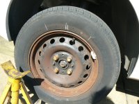
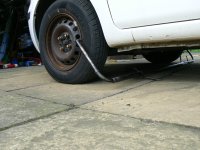
So what's the problem? Well, I've noticed that Becky's O/S/F - driver's side front - tyre is wearing slightly more rapidly on it's inner shoulder than over the rest of the tread width. Look here and you can see the inner shoulder (on the left) is wearing more than the rest:
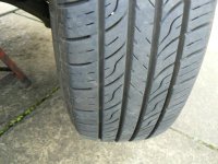
P1110100.JPG

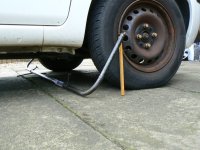
Compare this with the N/S and you can see the difference
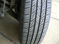
P1110101.JPG

Sorry, orientation of the pictures is confusing as the top one was shot from the rear and the one above was taken from in front of the car. In both pictures you're comparing the shoulder on the left of the picture.

So what I'm seeing here is the inner shoulder wearing more quickly on the O/S tyre but the tread wearing evenly on the N/S. This could be due to something bent or worn in the suspension on that side so the first thing to do is carefully and thoroughly check the suspension out on that side. So, Jack the car up and get an axle stand or two in for safety sake. People are often asking where to jack and/or put axle stands. Well, most cars will have reinforced jacking points on the sills but you can also jack or put stands under the subframe or body box sections Here's a picture showing how I've got a stand under the subframe:
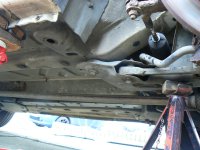
P1110104.JPG

But you can also see reinforced box sections - the bits with the holes in - that will happily take the weight of the car.

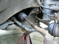
So, now it's safe and not going to fall on you, grip the wheel at the quarter to three position - one hand on the left and one on the right of the tyre and try to rock the wheel back and forwards. If you pull hard enough you'll be able to turn the steering - although the steering lock may click in if the key isn't in the ignition - but what you're looking for is play and you don't need to turn the steering to feel that. Now grip the wheel again at the six o'clock position - one hand at the top and one at the bottom and again try to rock it. Movement in this plane is more likely to be wheel bearing but you can also pick up on suspension joints.Might be in the bottom ball joint or track rod end:

P1110107.JPG


bottom ball joint is at the left hand end of that arm and the track rod end is a bit above and to the right of the convoluted CV boot. Shouldn't be any free play in them.People tend to forget that there's also a ball joint inside the steering rack dust gaiter. it tends to give itself away by allowing the track arm to jump in and out in a straight line if it's worn:
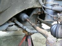
P1110103.JPG

It's inside the convoluted gaiter in the middle of the picture - you can see the track rod end in this picture too at the bottom right.

More difficult to ascertain is whether there's a problem with the rubber bushes on the inner ends of the bottom suspension arms. Here's Becky's:
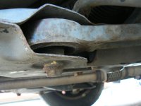
P1110109.JPG

That one is the rear one. Here's the front one:
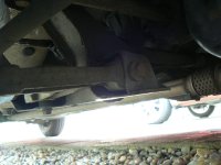
P1110108.JPG

Sorry, not a very good picture of that front one. The problem here is because they are rubber, unless they are absolutely falling to pieces, it's difficult to decide whether they need replacing or not. If you lever them with something like a crowbar or big screwdriver then, of course, they are going to give, they're made of rubber so they will, but how much give is acceptable - and this can be especially difficult to ascertain with void bushes if you're not used to them. (void bushes aren't solid rubber all through so they "give" more in one direction than another)

Quite a "neat" way to check them is, with the weight of the vehicle still on the ground, to put a power bar or similar tool on a wheel nut:
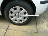
P1110106.JPG

Then push down and pull up on the bar and see if the wheel moves back and forwards in the wheel arch. If it does then something is worn and it may well be a rubber bush, especially if you've already checked out the ball joints. Get a helper to work the power bar while you take a look, it's usually easy enough to see where the play is.

If you're getting movement in any of these parts, there's no point trying to set up the toe in - which is what we're going to be doing. You need to sort out the worn bits by fitting new ones.

Ok, now we know our suspension and steering is sound, and I'll say again, don't waste your time trying to set up toe (or, for that matter, any other steering parameters like castor, camber. KPI etc) but we are only considering Toe here because it's reasonably achievable at home whereas the rest really needs professional equipment. Toe is also by far the most likely thing to be causing unusual tyre wear.

So what is "Toe". Well, quite simply, it's whether the front wheels have their front edges facing in the way - which would be toe in - and would cause the outer edges of the tyres to wear rapidly as well as feathering the tread pattern. Or, outwards, which causes the inner shoulders to wear and feather the rest of the tread in the other direction. Looking at the Haynes Manual for our Panda it tells me the toe setting is "Parallel" so the wheels are intended to roll down the road exactly parallel, neither pointing in towards each other or outwards. You might think that's obvious if you don't want to scrub life out of the tyres but not a bit of it. Many vehicles are set statically with a little bit of either toe in or toe out. This is because when the vehicle is rolling you need to compensate for movement in bushes and slight play in other components. It's not unusual to find a rear wheel drive car carries a little toe in because the front wheels, being undriven, tend to drag and splay outwards, particularly when braking whereas a front wheel drive car will be trying to make it's front wheels "squint" as they drive forward. This is however, not a "golden" rule, I've seen front wheel drive cars specified with toe in - can't remember a rear wheel drive with toe out though. You need to consult the manufacturer's specs.

Well, Becky is very slightly wearing the inside of her O/S/F tyre but not affecting her N/S tyre, strange? well no, not if the toe is set with only very slightly too much "out". If there's only slightly too much toe out then this wear pattern is common. But toe out means the two front wheels are splaying out slightly so that means the N/S is trying to go towards the kerb and the O/S is trying to go towards the white line in the middle of the road? Well yes, and if the degree of toe out is excessive then wear will be seen on the inside of both treads with the pattern feathered over the width of both tyres. However, our roads are cambered towards the kerb for rain runoff. None of us notice this but we subconsciously steer very slightly to the right to counteract this. What this means for those front tyres is that, if there is only a very small amount of excess toe out then the O/S (right hand side) wheel and it's tyre do indeed point slightly towards the middle of the road but but it is stopped from moving the vehicle in that direction by the influence of the camber and grip of the N/S (left hand side) wheel and tyre which are rolling straight ahead. Result? N/S tyre wears evenly but O/s wears on the inner shoulder - exactly what I have on Becky. So I'm expecting to find she has a very small amount of excess toe out. In fact I think that someone has, in the past, adjusted her toe incorrectly because her steering wheel is actually very slightly to the left when going in a straight line.

This thread is getting very long and I don't know if there's a limit. So I'm stopping it here and taking up again in minute down the page.
 
Last edited:
Ok, here we go again.

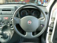
I started off by doing a very quick check with a straight edge to see where her wheels are pointing. So, sitting in the driver's seat, carefully set the steering wheel dead straight ahead:

P1110076.JPG

On modern cars, especially if there's electric power steering, this will set the rack to it's middle position because the rack pinion has a master spline which means the column can only be mated to it in one position. Likewise with most steering wheels, although the Panda actually just has alignment marks. If you've an older car without any power steering at all or maybe hydraulically assisted you need to check the steering wheel and rack are correctly aligned and I'm not doing that here.

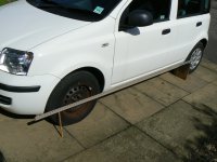
Having set the steering wheel I popped out and laid a straight edge along the N/S of the car:

P1110077.JPG

It's supported at wheel centre height by a suitable piece of scrap wood at the back and front with the edge touching the sidewall of the front of the rear tyre and both sides of the sidewall of the front tyre. Careful inspection of the front tyre in relation to the straight edge shows it to be touching on both sides of the sidewall.

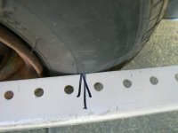
Repeating the exercise on the O/S and close examination shows there is a wee gap between the straight edge and the rearward sidewall Here's the front egde:

P1110080.JPG

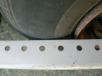
and here's the rear:

P1110081.JPG

It's only about a couple of mil but it means the front wheels are very slightly toed out, just waht I expected to find from what that O/S front tyre was telling me.

As you can see, we're not talking about very much here are we, but small differences can cause lots of unwanted tyre wear. The question is what to do about it? Well, if you've not got a reasonable tool kit and/or don't want to get your hands dirty, take it to a specialist. Trouble is how good a job gets done depends on the individual doing it and my experience is that lots of toe adjustments get botched. Sometimes because the operator is incompetent and doesn't properly check for worn components before starting. Sometimes because corrosion or damaged parts, like track rods and locking nuts, won't allow proper adjustment. Sometimes because the operator just doesn't give a **** and only roughly adjust to a barely acceptable standard. I think it's a greatly abused procedure.

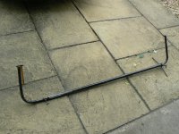
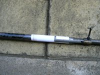
Setting toe is a really common task in a general workshop and one done at least a couple of times a week by many mechanics but you need special equipment which isn't worth buying for the infrequent use it gets at home - although there are some interesting DIY options available now a days - but I experimented for several years and, after several which didn't work very well, came up with this:

P1070364.JPG

Which consists of these component parts:

P1070363.JPG


The really important parts are the two tubes which must be a good sliding fit inside each other with no play, otherwise results won't be accurate.

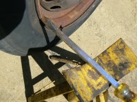
So how do we use it? Well, you've checked out all the suspension and steering as mentioned in the first post above? Ok, now your rims need to be checked because we're measuring quite small measurements here so on the Panda's rusty rims that meant running a big screwdriver blade against the riM as I rotated it to get a nice even measuring datum:

P1110073.JPG

In simple language I rotated the rim against the blade to bust the crusty bits off! Of course by now the wheel is jacked off the ground.

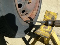
Then a smaller screwdriver is used, held stationary on the stand:

P1110074.JPG

While the wheel is rotated to check if it's running true by observing the gap between the end of the screwdriver and the rim. It needs to be running really true, an out of true wheel will make an absolute nonsense of the procedure. The O/S rim worked out very well but the N/S had a section where the gap between the end of the screwdriver and rim increased. I made a chalk mark where the depressed section started and where it ended. The rest of the rim was good, ie. no gap, so I put the depressed section to the top as my tool works at the quarter to three positions. you can just about see the chalk marks here:

P1110075.JPG

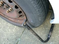
Now the car is put back on the ground and run backwards for a few car lengths - to the other side of the road in my case - then driven forwards again until it's where I want to work on it and the tyre chalk marks are as you see in that picture - at the top. Now the "Fixed end" of my tool is lined up with the axle centre of the O/S front wheel (hub caps off):

P1110083.JPG


and the lock is tightened - see screwdriver - on the stand. This sets the height of the "fixed" measuring stop and must not now be slackened while measurements are taken.

A piece of masking tape or paper is fixed to the end of the larger diameter slide tube:

P1110082.JPG

This is where the measuring marks will be made. The lock on the scribing bar is slack at this point so the scribing bar can slide up and down the smaller diameter slide tube.

The whole shebang is now slid under the front of the car:

P1110084.JPG


with the fixed stop resting against the front of the rim on the O/S:

P1110085.JPG

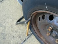
and the stop on the smaller diameter slide tube against the front of the rim on the N/S with a precisely measured wooden prop holding it at exactly axle centre height:

P1110086.JPG

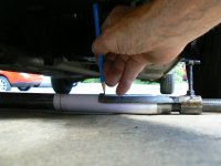
The scribing pointer is now moved to a position over the paper/tape and a sharp pencil, held at right angles to reduce the possibility of inaccuracy due to parallax, is used to scribe a line on the paper:

P1110087.JPG

The whole "shebang" is now withdrawn from the front and fed in under the car so that the fixed stop is now against the back of the rim on the N/S and the stop on the smaller sliding tube is against the back of the rim on the O/S.

P1110089.JPG

P1110088.JPG

Another line is scribed on the paper. It's very important that neither the stand clamp not the scribing bar lock is slackened at any time otherwise the scribed lines will be meaningless.

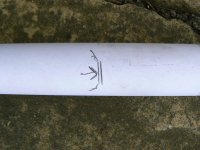
So now we have two lines on the paper, one taken with the tool in front of the axle and one from behind. By comparing the lines we can see the difference in distance between them and, knowing which line is the "in front line" and which the "behind", we can see whether it's a toe in or toe out situation.

P1110090.JPG

In this image I've marked the "behind" line with an arrow to make it clear, usually I just extend the line at it's end - as you can see - so I don't get confused as to which was "in front" and which "behind" The actual difference in this case is about 2.5mm. So you can see we're not dealing with big measurements. Ok. so the front of the rims are 2.5mm further apart than the rear. The recommended setup is parallel. The steering rack tie rod and track rod end are behind the axle centre line so I need to lengthen the tie rod to track rod end distance. This is simply done by unwinding the track rod out of the track rod end by a wee bit - you just have to guess at it but you get better as you do it more often.

Here's where my obsession with coating threads with copaslip pays off. The copaslip is wiped away to reveal a nice clean thread:

P1110103.JPG

And some WD40 introduced to the rack gaiter so it can spin on the track rod and not wind up and destroy itself:

P1110094.JPG

Then it's just a matter of unlocking the locknut, which can be a real pain on a badly corroded example, but I'd slaistered all that Copaslip on mine years ago - smirk!

P1110096.JPG


You'll see the big "stilson" type wrench which is stoping the force being applied to unlock the locknut with the black tool? It's so very important to support the trackrod end in this way. If you just rely on the ball end resisting the force of the spanner unlocking the locknut you can do great damage to the ball joint (track rod end) I've seen the whole joint separated completely! The biggest danger is that you partially damage it without realizing and it then goes in to fail sometime later - which could be catastrophic! I will turn the stilson round and support the track rod end again when I'm tightening the track rod lock nut.

Judging from the distance apart of the lines I've scribed I take a guess at winding the track rod out of the track rod end by half a turn. lengthening the effective distance from rack ball joint. I just nip up the locknut to take any backlash out of the threads, put the wheel back on, put the car back on the ground and reverse it across the road and back up to where I'm working, being careful to both ensure the chalk marks on the N/S tyre are at the top and that I don't let the car run back. It's important to travel forwards and stop without letting it run back which might introduce inaccuracies on an older car - it's just good practice to eliminate "unknowns".

The measurements are taken again, in front of the axle line and behind and the pencil marks are checked. My guess was pretty good but I've actually ended up with just a smidgeon of toe in now. I think about a sixth of a turn back in on the track rod will do it. So, with the locknut just nipped up, I can work on this without having to jack her up or remove the wheel by turning the steering full left lock. Do the adjustment and nip the nut up again - always nip the locknut up, there's enough backlash in some threads to mess with you. Run the car back and forwards again to settle it. Take the measurements again and this time? whohoo! the two lines are exactly over the top of each other - looks like just one line!

P1110110.JPG


I've marked them up 1, 2 and 3 for you the first one was on the left, then I did the one on the right but i stuck the third in the middle to keep it compact for taking the picture.

Just a matter of buttoning things up now. I could have tightened the locknut with the car on the ground but these creaky old bones find it easier these days with it up in the air and the wheel off for access. Took her for a run around on some nice straight bits of road and the steering wheel is now perfectly straight when going in a straight line. It's always had just a couple of degrees bias to the left since I bought her! should have attended to this years ago! She's got a very very slight tendency to want to pull left but I'm pretty sure that will be down to the uneven wear on the O/S tyre now that the toe is actually correct. I'll try swapping it with the N/S sometime and see what difference it makes but I want to check the gearbox oil level before I finish as I forgot to do it the other day when I was doing the oil change and brakes. Expecting a slight drop in level as there's a small leak, dampness really, at the gear selector shaft seal.

There you go. Gearbox oil level checked, no detectable drop in level!
 
Last edited:
Ps to the above. You'll notice I've made a lot of mention to the height of the measuring stops on the tool being level with the axle centre height? It's very important that this is observed because the wheels are not at right angles to the road surface, none are - well, pretty much none - because most have a degree or two of negative camber so if you don't take the measurements at the same height every time you'll get meaningless results.

Oh, and by the way, if you make marks on the sidewall then rub them off when you've finished. I was stopped once by the boys in blue and when I asked why they said it was because they noticed the yellow chalk marks on the tyre and wondered if a tyre store/garage had marked them because they were defective!
 
but I'm pretty sure that will be down to the uneven wear on the O/S tyre now that the toe is actually correct
That is a really interesting post. I have excess wear on Daffo too. I need to take it back for a recheck. I know I doo need an inner track rod end too so that is next on my to do list.
 
That is a really interesting post. I have excess wear on Daffo too. I need to take it back for a recheck. I know I doo need an inner track rod end too so that is next on my to do list.
As many on here will know, the first job I got after college was with Firestone's racing division. My "every day job" was to provide trackside support for our customers in the European Touring Car Championship. I was one of those chaps you would see rushing up to the car in the pits, as soon as it stopped moving, and "inexplicably" sticking a needle into the tyres! No, we weren't insane, the needle had a thermocouple in it's tip and what I was doing was taking temperature readings across the tread area from just inboard of the inner shoulder, the middle and just inboard of the outer shoulder. From these temperatures you could deduce how the car was "working" the tyre and make suggestions to the team as to whether you thought it needed more or less camber, harder or softer springs, increased or decreased stiffness of the anti roll bar and other "stuff".

Having done some 4 years full time study at college and getting some nice looking qualifications, I thought I knew it all regarding wheel alignment - Toe, castor, camber, king pin inclination, toe out on turns (Ackerman steering, or anti Ackerman even), roll centres, and more. Boy was I wrong! all my life I've found anything to do with tyres, suspension, steering etc absolutely fascinating.

That toe gauge of mine came about from me considering the old optical Dunlop Wheel Alignment tool: https://www.ebay.co.uk/itm/285409667776?hash=item4273bdeac0:g:gScAAOSwfLdkx9tt a tool with which I became very familiar later on when I went into the Tyre and Auto Stores. In fact it's somewhere around the Mk6 version, improving with each evolution. It looks crude and simplistic, and in many ways it is, but, if you're careful using it, it gets pretty close to the old Dunlop gauge in outcomes. Good enough that we really don't have tyre wear problems on any of the "Family Fleet".

The lengthy description of what I was doing to Becky in the posts above isn't intended to be a prescriptive account of how to do toe adjustment, although there's a good bit about it in there. So I thought people might be interested in a basic list of what's involved in trying to Do It Yourself on your driveway with some basic equipment, perhaps like my tool. By the way, Gunson (maybe now branded Laser?) sell a good "drive over" tool: https://www.gunson.co.uk/product/G4008/Trakrite-Wheel-Alignment-Gauge but it needs to be kept spotlessly clean. Any dirt in the mechanism and it won't give accurate results. There are others for DIY but I don't have any experience with them.
Ok, here's the list:

1) check all suspension and steering joints, bushes, arms, etc for any wear and/or damage. renew anything that's not nearly perfect.

2) Check the steering wheel is centred on the rack. What is he talking about? Ok, turn the steering wheel one way, either left or right, doesn't matter, until you hit the end stop. Now wind it back the other way until you hit the other stop, counting the number of turns as you go. Half that figure, so if it's gone 5 turns lock to lock what you need to remember is 2.5 turns. Now wind the wheel back by 2.5 turns and the steering wheel should be in the centre position - as you would want it to be when driving in a straight line. In real life it's rarely a nice round figure like this so you nearly always end up with an awkward figure to work out what half of is.

By doing this what you've done is to put the rack itself into it's middle position and you want the steering wheel to reflect this. Most modern cars have master splines on the rack so the column can only be fitted in the one position and the same with the steering wheel where it fits to the top of the column - The Pandas have a punched in mark on the top of the column and wheel boss. However many older cars aren't like this and the column and wheel can be fitted in any position. It was very common, back in the day, if a customer came in complaining that his/her steering wheel wasn't "straight" to simply undo the nut in the middle of the steering wheel, pull it off the top of the column, turn it until it looked "straight" and put it back on. The outcome of course was that the car then had more lock on way than the other. I've seen cars which were rubbing their tyres against the inner wing when on full lock because of this, potentially very dangerous!

3) With the steering wheel now straight on the column and set so it's in the straight ahead position, just to give you a rough idea of what's going on, you can "eyeball" the setup by kneeling in front of each front wheel in turn and looking along the outside of the wheel as it lines up with the rear wheel on that side. Many cars do not have the same track front and rear (distance the two rear wheels are apart at the rear compared to distance the two front wheels are apart) so doing this eyeball check doesn't tell you all that much but one very valuable thing it does tell you is whether both front wheels are toeing in, or maybe out, by roughly the same amount, which is what you would expect. Knowing if one wheel is pointing in, or out, by more than the other is useful as you continue because it lets you know one wheel is going to require more adjustment than the other. (also it's very quick to do, so why wouldn't you?)

4) Now you need to find out what the toe is actually set to. You've seen how I do this with my tool, you'll have to use whatever tool you've got. always roll the car forwards for a few yards, better yet drive it round the block, to settle the suspension before taking any fine readings and don't let it roll backwards after stopping as this can introduce inaccuracies due to compliance in rubber bushes and other "stuff". Consult the maker's specs to find out what they recommend and compare to what you've found the car is set too. Annoyingly my tool only facilitates measurement in linear scale (inches or millimetres) and some manufacturers give the toe in degrees and minutes! You may need to convert depending on how your tool is calibrated. There are scales available on the web if you look for them - I use one from Trackace.

5) So now you'll know whether your toe is correctly set or not. Even if it's set correctly all this is checking is the relationship of one front wheel to the other, ie, are they parallel, pointing in towards each other or splayed out away from each other - I'm thinking about this relative to forward motion of the vehicle. Even if set up correctly, it's quite possible for the steering wheel to not be in the straight ahead position when the car is going straight - this will be because one track rod has been screwed further into it's track rod end than the other. So our next check is with the straight edge, as I showed in the original post. Use something to hold it at wheel centre height on the rear wheel and against the front wheel on that side, again at wheel centre height - check out the picture - look carefully at the gaps between the straight edge and the front and rear sidewall on the front tyre. Repeat on the other side of the vehicle and the result should be the same. All the time with the steering wheel in the straight ahead position. If one side mirrors the other and the toe setting is as specified the, Hallelujah! You're done! More than likely though you're doing this because you've got a problem and you will find that either the toe setting is wrong or that one wheel is pointing in or out more than the other.

6) So everything isn't Ok? What you've got to do now is play with screwing the track rods in or out of the track rod ends as necessary, until you end up with the correct toe setting AND the straight edge gaps on one side exactly mirrored on the other, all with the steering wheel in the straight ahead position. Achieve that, lock up the track rod locking nuts and you're done! One wee hint I can give you is that if it's all getting close then probably the exposed length of thread on one side will be the same as that on the other. Very rarely though you might get an aftermarket track rod end that's different to the original, nothing wrong with that if it's good quality, but if it's casting is longer than the original equipment part then obviously you aren't compare exposed thread lengths. I think this is less likely these days though because so much stuff is OE quality so basically identical.

The first few times you try it you'll probably just about pull all your hair out, turn the air blue and think seriously of just chucking the car at the nearest garage or tyre store who can do this. However, as you get into it, you'll find it becomes intuitive as to which track rod, and by how much, to turn it. You'll notice in the account above I had a rough idea, because the wear was quite slight, on the one tyre only and that the other tyre looked to be wearing normally. That I wasn't going to have to turn the rod much and that it was probably all going to be needed on the O/S You can't really tell for sure but from past experience, it seemed very likely. I can't teach you that, it comes with doing it again and again. However you'll notice it only took me 3 tries to get it spot on - the more you do it the better you get at it. The lads in the garages/tyre stores have it easy these days with their, very expensive, Laser alignment tools where they attach a laser projector to the wheels and can then watch the beam projected against a scale as they do the adjustment. Takes minutes, as long as the adjusting rod and it's lock nut are not corroded to hell and back! The accuracy of the end result is still very dependent on the chap doing the job though. If you're paying for one of these alignments insist on the final print out the machine will deliver. You can't really fool the machine but the presetting checks are as important as ever. Fail to find a worn or damaged component and you may achieve a "text book" result but as soon as you drive the vehicle the worn or damaged part will reintroduce a variable which takes you right back to the problem you originally were trying to cure.

Of course, with my tool, you can only do front wheels. However, mostly, it's incorrect toe which causes tyre wear and correcting it will restore things to normal. There are a number of other parameters - I mentioned them above - Camber, K.P.I. etc - which can also affect steering and tyre wear but mostly these things are not adjustable and, if giving a wrong reading, will be due to accident damage and will need a body shop or someone with something like a Hunter Bench, to sort out. Rear tyres can also wear abnormally and some cars, most notably those made in the far east, have adjustment provision for the rear wheels. Most however do not, it's built in when the vehicle is manufactured so if it's wrong then very likely something is bent. Our Pandas seem to suffer from very variable quality control of the rear axle and some people on here have reported rear tyre wear which, when checked on something like the Hunter equipment I mentioned, are found to be outside the tolerances. rectifying this is not at all easy, some say impossible - so NEVER jack your Panda up in the middle of the rear axle beam. Bend it and all your rear wheel geometry will be out! Only cure? a new axle! check carefully, when buying, for signs of a jack having been in contact with the middle of the axle. But this could go down another "rabbit hole" so I'll stop here.

Hope someone has enjoyed this? please do chip in anybody else if you want to contribute or criticize my thinking.
 
Last edited:
This post contains affiliate links which may earn a commission at no additional cost to you.
For many years I've done my own front tracking. If I had serious problems with "odd" wear, like on my Croma 2005 which was notorious for excessive rear wheel camber wear, I would take the car to a proper 4 wheel alignment place that use the like of Hunter or SnapOn complex rigs.

https://www.hunter.com/en-int/alignment-machines/winalign-standard/

This type of kit checks all the geometry EVEN if the rims are not true. Rim deformation is calculated out (don'r ask me how).

Like you I've used two bits of kit. One, which I still have and trust, is an old Gunson Wheel.true device. It very much like your Dunlop guage but much more primitive. Basically two known length rigid bars/frame that strap to the wheel rims and extend infront and behind the wheels. You the use a steel tape measure to measure the distance bewteen the front-front and back-back. If the same then the toe is 0mm. Simple maths on wheel rim size and bar length gives the toe at the rim.

The other kit I had but gave away was a similar bar arrangment but extends to front only with protractor dials on the end to which you put elastic to joint them. This gave readings in degrees between the two bars.

When I had to do the rear wheel tracking on our 130TC (requires shimming the lower wishbone) I used a spirit level with laser. Park car up level with wall. Place level/laser along rim tire and then with a rule measure beam position on wall and front hub. Do same for other side. This allows you to check the offsets and that one or both wheels are pointing along the chassis line. You want the back axle to be square (90deg) to the chassis centre line. From there you know if the axis needs to be changed. Then you can measure and set the toe.

This is where things become a little more complex, but again fairly simple math / geometry.

I did this back in 1990 and still have the hand written 3 * A4 pages of calculations to work out the shimming changes required.

One reason for unequal front tyre wear due to tracking is because the car is crabbing. i.e. the back axle and rear tyre toe is offsetting the vehicle straight line. The front toe may be correct and the steering wheel level but everyting is skewed (or is that screwed).

Another thing that has to be checked is that the steering rack lock to lock is centered and the steering wheel is level. Cowboys in the old days would set the toe and if the steering wheel was not level the would just move it a spline or two. So that doen you set the tow and do a test drive. If the steering wheel is not straight on a level surface then you have to adjust BOTH wheels to correct and maintain the same toe. Bit of trial and error but has to be done.
 
One reason for unequal front tyre wear due to tracking is because the car is crabbing. i.e. the back axle and rear tyre toe is offsetting the vehicle straight line. The front toe may be correct and the steering wheel level but everyting is skewed (or is that screwed).
Mostly, doing anything about rear end misalignment is so much more difficult than front end stuff for the simple reason that the manufacturers seldom make any provision for adjustment. I notice my boy's Audi A4 has those little snail cam adjusters on the inner suspension arm mounts but adjustment (camber and toe I think) is carried out with the car loaded and you've just not got the room to do that unless it's up on a 4 poster or over a pit. I think rear end adjustments are best left to chassis specialists with, as you say, all the right gear.

That's not to say I've not thought about it often. It would be easy enough to use my tool to check the toe on rear wheels and to check the sides with the straight edge. That would tell me whether the toe is correct and if the rear wheels are running in line with the front wheels - and so, presumably, with the axis of the chassis. As has been posted on the forum in the past, with the Panda you can use shim washers under the 4 main hub mounting bolts to alter where the wheels are pointing and, if the wheels were found to be not running parallel with the centre line of the chassis (using the straight edge) you could add and subtract shims from one side or the other to effect small changes. If you're going to get that involved though you're going to need to be looking at camber too because the shimming could easily alter that. If larger change is required I've wondered if it could be done by elongating the 3 holes in the front axle mounts? you would than be able to move the axle back into line with the centre line of the vehicle. I don't seem to have any rear end problems with Becky - although I've not actually tried to take any measurements but tyre wear looks normal - It'll be interesting to see, If I have to fit a new back axle because of the spring pan corrosion, whether it ends up giving me problems.
 
Wrote a lote of good points - see post above
Mostly ...........

Pugglt Auld Jock

Wrote a lot of good / valid stuff above so see his post above.

Snail cams (not sure I would call them that) is what the Croma 2005 / Vectra Epsilon platform used. The early Croma's stripped the rear inside tyre treads very badly. The Fiat official technical bulletin which I think I still have gave the usual mitigation/acceptable wear criteria which was IMHO very much in their favour. Along with that bulletin if things needed to be adjusted then new and different cam bolts were required. As I recall problems still existed because the Fiat dealers did not have the advance pucker 4 wheel / chassis alignment equipment like the Hunter kit to properly setup the car.

I think what I find interesting here is how the old style simple beam and even non complex single wishbone suspension setups never ever gave an issue. It is the more modern multilink systems which are prone to issues. Yes they may be better (if you care to define that) but they seem to be far more sensitive to any misalignment, road pot hole thumps and bangs and general wear and tear and old age.

I'm really strugling to recall any issues with rear tyre wear / geomerty issues on Fiat cars of pre 2000 vintage. (Barring accident damage and rear wheel drive models - 124 - 131 - ? with drivers doing wheely spins and hamering the pedal to the metal).

That said older vehicles were in the 20HP to 100HP range and not as such performance / sport's stars. Today's cars with 100+ BHP to 200+ coupled with required comfort, smooth ride, low noise, improved handling for these bigger and heavier chassis etc. has meant that simpler suspension systems needed to be enhanced. So I guess we/public are to blame for the transition from "keep it simple" to "rocket science" and the resulting fragility and tetchy systems we have today.
 
As usually informative technical detail from @Pugglt Auld Jock.
In the neglected state of what's left of my garage gear is my Dunlop Wheel Alignment Gauge. Oh! and a few of my Stilson type wrenches in answer to Jock's "You'll see the big "stilson" type wrench" and with apologies to Crocodile Dundee "Nah, this is a Stilson", unless of course someone on Forum has a bigger one;););)
 

Attachments

  • DSCF0932.JPG
    DSCF0932.JPG
    470.7 KB · Views: 35
One front wheel wearing different to the other side will never be cured by adjusting the toe

Toe will always wear both sides the same assuming

Both tyres are the same and at the same pressure

And the car isn't driven like a hooligan

In my youth the outside of the NSF use to always wear out first due to sliding round rounderbouts.
 
In my late teens I owned a Mk 4 Ford Zephyr V6 which with my "enthusiastic?" driving I returned 12 Mpg @ 35pence per 4.5litres(gallon) and thought drifting was the normal way to corner, strangely the 6.70 x 13 crossply tyres didn't seem to last very long. I had to sell that car when fuel price rose to an exorbitant 65pence per 4.5 litres(gallon) wish it was that price now!!!;)
 
In my late teens I owned a Mk 4 Ford Zephyr V6 which with my "enthusiastic?" driving I returned 12 Mpg @ 35pence per 4.5litres(gallon) and thought drifting was the normal way to corner, strangely the 6.70 x 13 crossply tyres didn't seem to last very long. I had to sell that car when fuel price rose to an exorbitant 65pence per 4.5 litres(gallon) wish it was that price now!!!;)
In my late teens I could put enough petrol in my wee Mini to travel from Galashiels, my home town, up to Paddy's Bar in Rose Street, Edinburgh (about 30 miles), where I would meet up with the crowd I knocked about with (included the future Mrs J), have a couple of beers and buy the future Mrs J a G&T or something else, maybe a lemonade shandy? drop her off at her house on my way home - a diversion of about 5 miles - drive back down to Gala - and usually find I'd spent about £5, sometimes £6 if I'd really pushed the boat out and bought her more than one drink!
 
As usually informative technical detail from @Pugglt Auld Jock.
In the neglected state of what's left of my garage gear is my Dunlop Wheel Alignment Gauge. Oh! and a few of my Stilson type wrenches in answer to Jock's "You'll see the big "stilson" type wrench" and with apologies to Crocodile Dundee "Nah, this is a Stilson", unless of course someone on Forum has a bigger one;););)
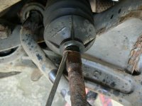
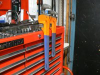
I thought I had a big one! but I think you've got me beat Mike:

P1110111.JPG

Mine measures 18" from top to toe and it's never failed to deal with anything I've attacked with it! for comparison behind it is the one I was using on Becky's track rod end. I've also a smaller one, they came in a set of three, which lives in my plumbing tool box.

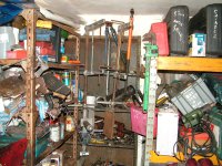
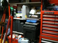
Mrs J is always getting on at me about how chaotic my garage storage is, this shelf is pretty representative:

P1110112.JPG

However I think you've got me well beat in the "chaos" stakes.
Most of the former mechanics I know seem to have garages full of "stuff" just like us. It must be some sort of disease the trade infects you with. Although much of it looks like a chaotic collection of old rubbish, there's nothing in my garage that might not be useful one day! Unfortunately neither of my boys seem to have any interest in my "hobby" so Mrs J says, if I die before her, she's going to get a big skip in and just chuck everything except my tools in it. Not sure what she has planned for the tools though!
 
I am sure your good lady would revise her opinion of your garage if she visited mine:).
The Stilson copy is still able to grip at around 36inches so a fair bit of leverage when accompanied by a "fat git like me" even if the muscle side has deteriorated over the years I know how to use the weight to advantage;).
I do also have a "small one" Stilson that is, a genuine one I bought at another auction still in it's packing and has proved incredibly useful for badly rounded brake pipe unions that no brake pipe spanner could grip and yet that lovely wrap around action of the little Stilson worked every time. Obviously replacing the pipe and unions using new Kunifer brake pipe using my Sykes Pickavant Flaring Tool.
I notice the LandRover ladder/farm jack another useful tool in your photo, when I bought one of my boats it was on a very rusty 16 inch twin wheeled 3.5 tonne trailer and had been standing there since before 1982, I was able with bulks of timber and the ladder jack against a wall move it sideways away enough to gain access to then get it decanted to a new trailer on loan prior to putting it on as mooring in the harbour where over the next two years I removed the V6 Volvo Penta 150hp(Buick engine) and fitted the Fiat Ducato 2.8 Sofime engine I marinised, every engine lifting exercise involved running it up the slipway between tides, sealing up again to prevent sinking and then returning to it's moorings, all done single handed using a 1.5 tonne engine crane and tools that had to be loaded back into van before the water crept back in again. All done with the permission of a friendly harbour master sadly no longer with us.
 
Last edited:
I am sure your good lady would revise her opinion of your garage if she visited mine:).
The Stilson copy is still able to grip at around 36inches so a fair bit of leverage when accompanied by a "fat git like me" even if the muscle side has deteriorated over the years I know how to use the weight to advantage;).
I do also have a "small one" Stilson that is, a genuine one I bought at another auction still in it's packing and has proved incredibly useful for badly rounded brake pipe unions that no brake pipe spanner could grip and yet that lovely wrap around action of the little Stilson worked every time. Obviously replacing the pipe and unions using new Kunifer brake pipe using my Sykes Pickavant Flaring Tool.
I notice the LandRover ladder/farm jack another useful tool in your photo, when I bought one of my boats it was on a very rusty 16 inch twin wheeled 3.5 tonne trailer and had been standing there since before 1982, I was able with bulks of timber and the ladder jack against a wall move it sideways away enough to gain access to then get it decanted to a new trailer on loan prior to putting it on as mooring in the harbour where over the next two years I removed the V6 Volvo Penta 150hp(Buick engine) and fitted the Fiat Ducato 2.8 Sofime engine I marinised, every engine lifting exercise involved running it up the slipway between tides, sealing up again to prevent sinking and then returning to it's moorings, all done single handed using a 1.5 tonne engine crane and tools that had to be loaded back into van before the water crept back in again. All done with the permission of a friendly harbour master sadly no longer with us.
Ah yes, the "farm" jack! an indispensable tool in the right situation. I wonder if people might be interested enough in my experience with mine to warrant starting a new thread? Oh what the hell, I'm going to go for it! Think I'll head it up "My Farm Jack - and what I do with it."
 
Great informational posts as usual jock

Can see your former trainer side coming though with posts like these
Yes, I'm afraid I do go on a bit sometimes. The family always jokes about the occasion when my younger boy asked something about his plumbing system. shortly after I started trying to reply to his question he erupted with "Dad, I only wanted to know why the b****y tap was dripping, not the entire history of plumbing since the Roman empire"! Mrs J delights in bringing this sort of thing up at the most inopportune moments!
 
Yes, I'm afraid I do go on a bit sometimes. The family always jokes about the occasion when my younger boy asked something about his plumbing system. shortly after I started trying to reply to his question he erupted with "Dad, I only wanted to know why the b****y tap was dripping, not the entire history of plumbing since the Roman empire"! Mrs J delights in bringing this sort of thing up at the most inopportune moments!
It's age Jock, my children are the same, however they still know where to come for help!!!
I have said to them if when they understand what I have told them they simple say, "Oh Dad, I see now , thanks" I would stop at that point however if one is still getting a vacant look, then the explanation will continue.;)
 
Last edited:
Back
Top