Introduction
Well starting this is well overdue although technically it's still just a car and a big pile of bits at the moment. It will come together quickly though as I have access to a commercial garage in the evenings and on weekends which belongs to a good friend. I'm lucky enough to have another good friend who is a self employed coded welder/fabricator and yet another good friend who owns a powder coating business. Myself, I do electronics so pretty much everything is covered. 
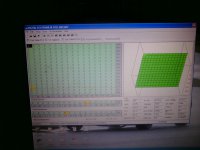
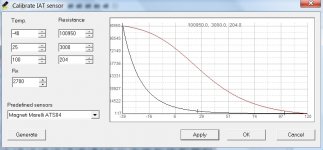
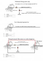
I'm not going to go into minor details as most of it has been discussed before (especially the engine which was purchased from Gazzaman). However I will answer any questions and will go into detail with the DET 3 setup and installation as there are no UK guides I'm aware of for this.
So the car:

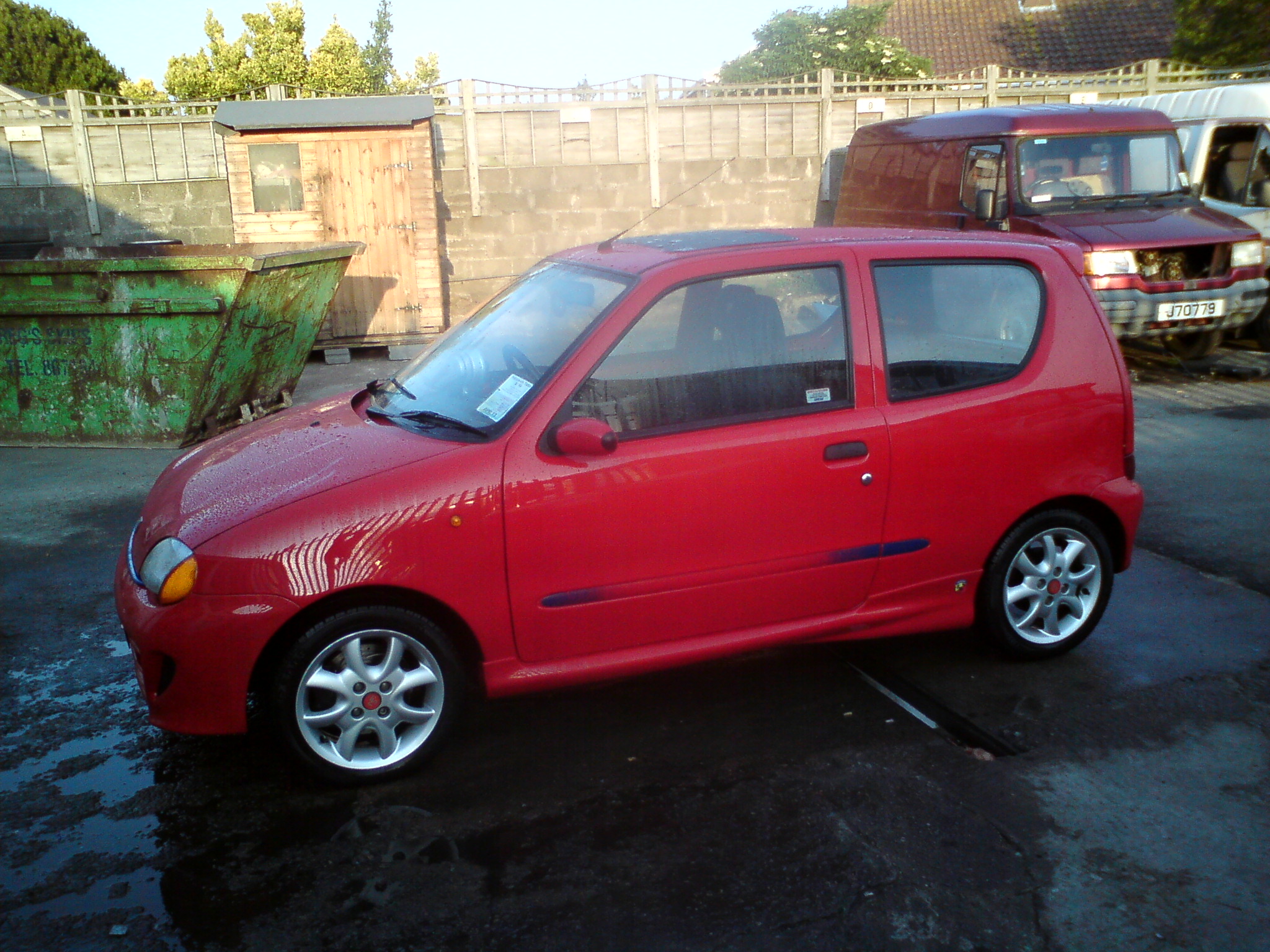
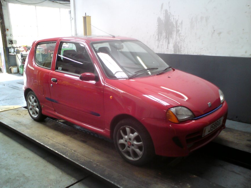
A 2000 SPI Seicento Abarth (probably manufactured late 1999) which replaces the silver Cinq (SPI Turbocharged) I have recently sold for restoration. The silver chap needed some TLC due to a bad repair from a rear collision before I purchased him. Someone made me an offer I couldn't refuse so I sold him on with the standard engine and pinched Mrs. Honeymonsters Sei after buying her a newer yellow ragtop replacement which I got a good deal on but wasn't really suitable for my project.
The planned spec is as follows, only thing I'm missing is the TB. Now Sorted (thanks Blu!)
Specification
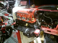
1.2 Punto 75 Engine
Fully balanced rebuilt bottom end and crank
Ported Punto 75 MPI head with 3 angle cut valves
866 Cam with Piper vernier adjustable pulley
16v pistons/rods with skimmed block/head to adjust for suitable turbo compression
Port matched HT coated Punto 75 inlet manifold with rebuilt and tested Larger MGF VVT Injectors
Strongflex Polyurethane engine mounts
HKS mushroom filter
ECU Master ECU using fuel implant technology running MPI and solenoid boost control
Brand new GT17 Turbo with Forge racing billet actuator
Custom tigg welded GT17 exhaust manifold with high temperature coating
Forge racing billet Dump valve
Upgraded Fuel pump
Adjustable Boost referencing fuel pressure regulator
Lightened 1.2 flywheel with C&G clutch
Custom exhaust/downpipe with Magnex stainless steel silencer
Renault 5 Turbo polished and uprated Intercooler with Samco pipes and stainless bends
9 row oil cooler with Stainless braided lines
Kinugawa Stainless braided turbo water and oil feeds
Modified brand new sump tig welded for oil return and breather
Aluminum oil catch can with baffle and breather filter
Lower temperature 85c thermostat
New pumps, belts, tensioners
New leads and custom injector loom
All new seals rings and bearings
Aluminum radiator
Sparco strutbrace
Quaiffe ATB differential with new drive shafts and cv joints
Uno turbo or Punto GT Calipers (have both) with vented/grooved discs and pads
-40mm springs and upgraded shocks
Hel Braided brake lines
Monroe adjustable camber bolts (Corrected thanks Brooky
New tie rods and track rod ends
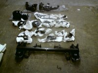
All suspension components including rear beam, arms etc. and front hubs, arms etc. removed and powder coated black.
Momo steering wheel, pedals and gear knob
Soundsream old skool reference series amplifier
Soundstream high end 6.5" component speakers
Image dynamics IDQ10 sub hidden in the spare wheel well.
Orion Ultra rare old school digital parametric equaliser
Audio control ESP2 spatial restoration unit
Alpine F1 Head Unit
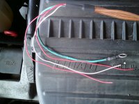
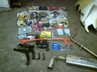
I will just post some pictures of the bits for now and then intermittently as I fit them.
I do however need to keep this car mobile to park it back in my workshop so it will be done in big chunks.
Cheers
I'm not going to go into minor details as most of it has been discussed before (especially the engine which was purchased from Gazzaman). However I will answer any questions and will go into detail with the DET 3 setup and installation as there are no UK guides I'm aware of for this.
So the car:
A 2000 SPI Seicento Abarth (probably manufactured late 1999) which replaces the silver Cinq (SPI Turbocharged) I have recently sold for restoration. The silver chap needed some TLC due to a bad repair from a rear collision before I purchased him. Someone made me an offer I couldn't refuse so I sold him on with the standard engine and pinched Mrs. Honeymonsters Sei after buying her a newer yellow ragtop replacement which I got a good deal on but wasn't really suitable for my project.
The planned spec is as follows, only thing I'm missing is the TB. Now Sorted (thanks Blu!)
Specification
1.2 Punto 75 Engine
Fully balanced rebuilt bottom end and crank
Ported Punto 75 MPI head with 3 angle cut valves
866 Cam with Piper vernier adjustable pulley
16v pistons/rods with skimmed block/head to adjust for suitable turbo compression
Port matched HT coated Punto 75 inlet manifold with rebuilt and tested Larger MGF VVT Injectors
Strongflex Polyurethane engine mounts
HKS mushroom filter
ECU Master ECU using fuel implant technology running MPI and solenoid boost control
Brand new GT17 Turbo with Forge racing billet actuator
Custom tigg welded GT17 exhaust manifold with high temperature coating
Forge racing billet Dump valve
Upgraded Fuel pump
Adjustable Boost referencing fuel pressure regulator
Lightened 1.2 flywheel with C&G clutch
Custom exhaust/downpipe with Magnex stainless steel silencer
Renault 5 Turbo polished and uprated Intercooler with Samco pipes and stainless bends
9 row oil cooler with Stainless braided lines
Kinugawa Stainless braided turbo water and oil feeds
Modified brand new sump tig welded for oil return and breather
Aluminum oil catch can with baffle and breather filter
Lower temperature 85c thermostat
New pumps, belts, tensioners
New leads and custom injector loom
All new seals rings and bearings
Aluminum radiator
Sparco strutbrace
Quaiffe ATB differential with new drive shafts and cv joints
Uno turbo or Punto GT Calipers (have both) with vented/grooved discs and pads
-40mm springs and upgraded shocks
Hel Braided brake lines
Monroe adjustable camber bolts (Corrected thanks Brooky
New tie rods and track rod ends
All suspension components including rear beam, arms etc. and front hubs, arms etc. removed and powder coated black.
Momo steering wheel, pedals and gear knob
Soundsream old skool reference series amplifier
Soundstream high end 6.5" component speakers
Image dynamics IDQ10 sub hidden in the spare wheel well.
Orion Ultra rare old school digital parametric equaliser
Audio control ESP2 spatial restoration unit
Alpine F1 Head Unit
I will just post some pictures of the bits for now and then intermittently as I fit them.
I do however need to keep this car mobile to park it back in my workshop so it will be done in big chunks.
Cheers