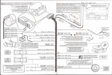
I’m installing a Cobra 4908 can bus alarm to my (New Model) 2007 Scudo 120 multijet. I’m looking for guidance on the attached installation instructions, which describes the exact fuse board plugs, pin numbers and colours of wire used to connect to the alarms harness.
Thanks to bigdong’s reply to my initial request (See thread in Scudo section) I’ve discovered that the wire colours described within the Cobra illustration pdf are incorrect.
My request for help consists of three questions.
Can someone please confirm/cross-refer the correct colours of the wires used by the plugs/pins described in the Cobra alarm fitting instructions pdf? This will be of great help to me when trying identi
Explain how the 10Kohm resistor connects to the system?
If I disconnect any of the plugs on the fuse board will this damage the vehicles electrical system?
Thanks again.")
Thanks to bigdong’s reply to my initial request (See thread in Scudo section) I’ve discovered that the wire colours described within the Cobra illustration pdf are incorrect.
My request for help consists of three questions.
Can someone please confirm/cross-refer the correct colours of the wires used by the plugs/pins described in the Cobra alarm fitting instructions pdf? This will be of great help to me when trying identi
Explain how the 10Kohm resistor connects to the system?
If I disconnect any of the plugs on the fuse board will this damage the vehicles electrical system?
Thanks again.