Technical 2010 ducato multijet radiator fans

Currently reading:
Technical 2010 ducato multijet radiator fans

AP9746

New member
Joined
May 22, 2016
Messages
4
Points
2
My 2010 ducato multijet glass a proem
With both radiator fans

Both fans come on almost as soon as the engine is started and stay running until the engine is turned off.

The water temperature sensor works correctly and the leads to the ECU have been checked there are no d breaks or shorts

The ECU has been sent away and tested and no faults were found.

Switching the aircon on or off makes no difference

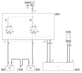
Both fan relays are in perfect working order

Testing the negative coil connections with the ignition on gives a reading of 3.7v + the positive connections being 5v+

Within seconds of starting the engine the coil negative connections drop to zero allowing both relays to operate

So far nobody on the internet has come up with the cause of this fault and how to rectify it does anyone in here experienced this fault and if they did what was the solution
 
Hi,
Although I do not have x250 data to refer to, I was not happy with your voltage readings taken at the negative end of the fan relays. A forum search revealed a diagram provided for a similar thread by @Anthony489, attached. The positive side of the fan relay coils is permanently connected to +12V, and the negatives are switched by the ECU. You should always read a nominal 12V on either side of the coils when using a modern multimeter, as the coil resistance is only about 120 Ohms. Is it the case that you have been using one of the M5 fusebox cover bolts as a negative connection for your meter. If this is the case then repeat your measurements with the meter earthed to an engine lifting lug, or other viable earth point. (On my x244 the M5 cover bolts are mounted in the plastic fusebox base.)

If the above has revealed a "red herring", then a wiring fault is a possible cause. The thread that I referred to above can be seen here but it was different, and no resolution was given. It does however mention a broken wire connecting to the ECU.
I am wondering if there could be a short in the wiring with a wire the goes to 0V when the engine is started. Unfortunately items like the main injection and LP fuel pump relay are operated before the engine is started.... In the same vein, is there any history or suspicion of water ingress into the engine bay fusebox?

Another thought is the engine block to chassis earth strap. Has this been replaced, as older ones are a known source of electrical gremlins. Can be checked by using a temporary jump lead between engine and clean chassis connection.
 

Attachments

  • X250 Cooling Fan Schematic 1.jpg
    X250 Cooling Fan Schematic 1.jpg
    47.6 KB · Views: 42
Hi,
Although I do not have x250 data to refer to, I was not happy with your voltage readings taken at the negative end of the fan relays. A forum search revealed a diagram provided for a similar thread by @Anthony489, attached. The positive side of the fan relay coils is permanently connected to +12V, and the negatives are switched by the ECU. You should always read a nominal 12V on either side of the coils when using a modern multimeter, as the coil resistance is only about 120 Ohms. Is it the case that you have been using one of the M5 fusebox cover bolts as a negative connection for your meter. If this is the case then repeat your measurements with the meter earthed to an engine lifting lug, or other viable earth point. (On my x244 the M5 cover bolts are mounted in the plastic fusebox base.)

If the above has revealed a "red herring", then a wiring fault is a possible cause. The thread that I referred to above can be seen here but it was different, and no resolution was given. It does however mention a broken wire connecting to the ECU.
I am wondering if there could be a short in the wiring with a wire the goes to 0V when the engine is started. Unfortunately items like the main injection and LP fuel pump relay are operated before the engine is started.... In the same vein, is there any history or suspicion of water ingress into the engine bay fusebox?

Another thought is the engine block to chassis earth strap. Has this been replaced, as older ones are a known source of electrical gremlins. Can be checked by using a temporary jump lead between engine and clean chassis connection.
Thanks for your reply I am afraid that the voltage readings I gave were incorrect I took them with the relay removed the correct readings were 12v+ at the live terminal and 3.7v + at the negative terminal switching to 0 almost immediately that the engine starts but just to make certain I will take the voltage at both terminals with the relay inserted. One other thing using a scanner to take the live data reveals that the temperature sensor is working as the water temperature rises steadily so it appears that the input side to the ecu is correct I will keep you updated as this progresses
 
Back
Top