Technical Multipla 1.9 JTD Front wishbone replacement: full procedure

Currently reading:
Technical Multipla 1.9 JTD Front wishbone replacement: full procedure

MarkX

Member
Joined
Mar 21, 2013
Messages
314
Points
62
Hi.

I've just replaced the 2 front wishbones on my Multi 1.9 JTD. Posted below is the step-by-step procedure I followed with pics.

My procedure is adapted from the PDF guide on the Fiat Microsite - https://docs.google.com/viewer?a=v&p...YzJmNzJhMWEzNg - with what I think are a couple of improvements to make the job easier, which are:

1. Jacking up the wheel hub to take the load off the wishbone brackets, simplifying removal of the old wishbone and installation of the new wishbone.

2. Correct installation of the wishbone balljoint pin into the pinch bolt clamp.

Disclaimer: You follow this procedure at your own risk, but it worked for me with no mishaps.

Mark
 
Last edited:
Equipment required

Tools:
- Car jack, wheel nut wrench, and axle stand
- Socket wrench
- 17mm socket
- 17mm spanner
- 10in (25cm) socket wrench entension, or similar length/sized drift
- Hammer
- Allen key, thin 17mm spanner, or nut splitter (whatever you use to remove a drop link nut/drop link)
- Trolley or other jack
- 13mm socket, and 3in (75mm) socket extension
- 15mm socket
- Wire brush, or wire brush attachment on power drill (not required if using new wishbone bolts)
- Crowbar or other lever
- Long 4-5ft (1.5m) lever
- Centre punch
- Torch
- Torque wrench 20Nm to 100Nm

Sundries:
- WD40 or similar
- Threadlock

Parts:
- New wishbone
- New wishbone bolts
- New wishbone pinch bolt and nut
- New drop link nut, or new drop link
 
Procedure summary

REMOVE THE OLD WISHBONE:

Step 1: Jack up car on relevant side. Support on axle stand. Remove road wheel.

Step 2: Remove the pinch bolt which secures the wishbone balljoint pin in the pinch bolt clamp.

Step 3: Loosen the wishbone balljoint pin in the pinch bolt clamp.

Step 4: Detach the drop link top balljoint from the strut.

Step 5: Jack up the wheel hub until the wishbone is horizontal.

Step 6: Loosen ARB bracket bolts.

Step 7: Remove the 4 wishbone bolts.

Step 8: Remove the wishbone balljoint pin from the pinch bolt clamp.

Step 9: Remove the old wishbone off the car.


INSTALL THE NEW WISHBONE:

Step 10: Test each new/cleaned up wishbone bolt in it's respective hole in the new wishbone.

Step 11: Place the new wishbone in position on the subframe.

Step 12: Install and fully tighten the 4 wishbone bolts.

Step 13: If possible, locate the tip of the balljoint pin into the mouth of the pinch bolt clamp.

Step 14: Lower the wheel hub back down, and remove the jack.

Step 15: Fully install the wishbone balljoint pin into the pinch bolt clamp.

Step 16: Install the pinch bolt and nut, and tighten fully.

Step 17: Retighten the ARB bracket bolts.

Step 18: Reattach the drop link balljoint to the strut.

Step 19: Install the road wheel. Lower car to ground. Torque up the wheel nuts.
 
Procedure in detail

REMOVE THE OLD WISHBONE:

Step 1: Jack up car on relevant side. Support on axle stand. Remove road wheel.
 
Step 2: Remove the pinch bolt which secures the wishbone balljoint pin in the pinch bolt clamp:

The pinch bolt is at the bottom of the wheel hub, nut and bolt are 17mm (see photos). I squirted on some WD40 before removal with a 17mm socket and wrench, and a 17mm spanner.

Photos:
- Pinch bolt head
- Pinch bolt nut
- Balljoint and pinch bolt clamp (pinch bolt removed)
 

Attachments

  • 1 Pinch bolt.JPG
    1 Pinch bolt.JPG
    99.5 KB · Views: 40
  • 2 Pinch bolt.JPG
    2 Pinch bolt.JPG
    66.7 KB · Views: 32
  • 3 Wishbone balljoint (minus pinch bolt).JPG
    3 Wishbone balljoint (minus pinch bolt).JPG
    124.1 KB · Views: 67
Last edited:
Step 3: Loosen the wishbone balljoint pin in the pinch bolt clamp:

To loosen the pin, there are 2 triangular projections underneath/either side of the wishbone balljoint (see photos). These are struck downwards alternately to loosen and drive the pin down the clamp.

I used a 10in socket wrench extension bar positioned at the back of the wheel hub on top of the projection (see photos). Then hit down on the extension bar with a hammer (Caution: mind the brake pipes!). Then do the same on the other side. Repeat as necessary, alternating sides until the pin is loose/has moved down the clamp. It is not necessary to fully remove the pin at this stage.

Tip: Turning the steering/wheel hub left or right gives better visibility and access to the projections on the wishbone.

Photos:
- Left projection
- Right projection
- Extension bar in position over the left projection
- Extension bar in position over the right projection
 

Attachments

  • 4 Left projection.JPG
    4 Left projection.JPG
    97.6 KB · Views: 36
  • 5 Projection right.JPG
    5 Projection right.JPG
    110.1 KB · Views: 34
  • 6 Extension bar left.JPG
    6 Extension bar left.JPG
    128.2 KB · Views: 39
  • 7 Extension bar right.JPG
    7 Extension bar right.JPG
    118.8 KB · Views: 37
Last edited:
Step 4: Detach the drop link top balljoint from the strut:

(This step is to make jacking up the wheel hub/wishbone in the next step easier by eliminating the resistance from the ARB/drop link pulling down on the strut)

a) Remove the drop link top balljoint nut - by whatever means you normally use (I use a nut splitter) (see photo). You will need a new nut when reassembling (or just take off the whole drop link and replace, whichever).

b) Jack up the wheel hub to take the load off the drop link, and detach the drop link top balljoint from the strut, as follows:

i. Put the car in gear (to stop the brake disc/hub rotating off the jack, when you jack up the wheel hub).

ii. To jack up the wheel hub, I used a trolley jack placed on the outside of the wheel hub, with one of the lugs on the lifting cup (on my jack they are at N, S, E and W) located into the gap between the inner and outer brake discs. The outer brake disc sits on top of the lifting cup (see photos).

iii. Jack up until there is no load from the strut/strut bracket on the top balljoint bolt, so that the top balljoint can be easily removed from the strut.

Note: You may want to place some kind of cushioning material between the jack and the brake disc. I may be replacing my brake discs so I am not worried about placing the jack directly onto them. I couldn't see any damage done apart from a bit of rust braking off the edge of the disc.

Photos:
- Drop link top nut removal
- Jack under brake disc/wheel hub
- Jack lifting cup
- Jack under brake disc/hub close up
 

Attachments

  • 11 Jack under hub close up.JPG
    11 Jack under hub close up.JPG
    180.3 KB · Views: 31
  • 10 Jack lifting cup.JPG
    10 Jack lifting cup.JPG
    157.3 KB · Views: 26
  • 9 Jack under wheelhub.JPG
    9 Jack under wheelhub.JPG
    254.9 KB · Views: 37
  • 8 Top link removal.JPG
    8 Top link removal.JPG
    95 KB · Views: 46
Last edited:
Step 5: Jack up the wheel hub until the wishbone is horizontal:

(This step takes the load off the wishbone brackets, making removal, insertion and positioning of the wishbone much easier)

Having removed the top of the drop link from the strut, ***Carefully*** continue jacking up until the wishbone is as near to horizontal as possible. Carefully, because some of the car's weight may shift onto the wheel hub and jack off the other means of support (similarly when lowering the jack and wheel hub back down later, the car's weight may shift back onto the other means of support).
 
Step 6: Loosen ARB bracket bolts:

(When removing the old wishbone and installing the new wishbone, this step provides clearance to slide the rear wishbone bracket under the ARB)

2 x 13mm bolts (see photo). 13mm socket, wrench and short 3in extension required.

For anyone who hasn't tackled the ARB bracket bolts before, access to the 2 bolt heads is via 2 holes underneath the subframe. The corresponding nuts on top of the bracket are captive nuts welded to the bracket.

Note: To get the necessary clearance, I found that it is not necessary to undo the bolts completely. (Leaving the bolts still attached to the ARB bracket, later, on wishbone installation, allows you to lever the wishbone bracket down onto the subframe via a lever placed between the ARB and the top of the wishbone bracket).

Photo:
- ARB bracket bolt locations
 

Attachments

  • 12 ARB bracket bolts.JPG
    12 ARB bracket bolts.JPG
    163.2 KB · Views: 45
Last edited:
Step 7: Remove the 4 wishbone bolts:

All 4 are 15mm hex head bolts. 15mm socket and wrench required.

The bolt heads are underneath and proud of the subframe. The corresponding nuts on the front, steel bracket are captive nuts welded to the top of the bracket. There are no nuts for the rear bracket bolts, the bolts screw into threaded holes in the aluminium bracket.

I found the longest bolt at the back of the aluminium bracket to be the tightest.
It might help to squirt some WD40 on the front steel bracket/bolts first.

Photos:
- Front (steel) wishbone bracket and bolt locations
- Rear (aluminium) wishbone bracket and bolt locations
 

Attachments

  • 13 Front bracket bolts.JPG
    13 Front bracket bolts.JPG
    169.9 KB · Views: 38
  • 14 Rear bracket bolts.JPG
    14 Rear bracket bolts.JPG
    162.5 KB · Views: 39
Last edited:
Step 8: Remove the wishbone balljoint pin from the pinch bolt clamp:

It should be loose already, so should come out quite easily once the wishbone bolts are removed.
 
Step 9: Remove the old wishbone off the car:

The more horizontal the wishbone the easier it will be to remove. First I slid the rear aluminium wishbone bracket out (rotating the wishbone clockwise) from under the ARB/off the subframe, then slid the front, steel bracket out. It's easy! (the procedure is reversed on refitting).
 
INSTALL THE NEW WISHBONE:

Step 10: Test each new/cleaned up wishbone bolt in it's respective hole in the new wishbone:


Before installation of the new wishbone, run each bolt in and out of it's respective wishbone bracket hole to make sure there are no problems, that they fit OK.

Note: If you are re-using the old bolts, they will probably need cleaning up to remove corrosion, aluminium and threadlock clogging the threads. Wire brush or wire brush attachment on a power drill would be useful. I used new bolts.
 
Last edited:
Step 11: Place the new wishbone in position on the subframe:

This is what worked for me...

This is the reversal of Step 9 ie. first slide the front, steel wishbone bracket into position on top of the front of the subframe, then rotate the wishbone anti-clockwise to slide the rear, aluminium bracket under the ARB and into position on top of the rear of the subframe. To do this, you may have push the wishbone balljoint down a bit to clear it under the hub. Easy peasy. Again: the higher you have jacked the wheel hub, the more horizontal the wishbone, the easier it is to install.
 
Step 12: Install and fully tighten the 4 wishbone bolts:

Note: I applied threadlock to each bolt prior to installation.

Bolt installation order: this is what I did:

- First: short bolt, steel wishbone bracket, loosely.

- Second: short bolt, aluminium bracket, loosely.

The above 2 installed provides good initial positioning of the wishbone.

Now for the two longer, trickier bolts:

- Third: longest bolt, aluminium bracket. Centre the bracket back hole over the subframe hole ("how to" tip below), then place a lever (I used a crowbar) between the ARB and the top of the wishbone bracket, and lever the bracket down onto the subframe. Insert the bolt from below through the subframe and into the bracket hole. It can be a little tricky getting the bolt started in the bracket hole, because it appears that with the aluminium bracket the bolt has to be perfectly aligned with the bracket hole to bite (took me 3 goes) (this is why I think it's a good idea to test the bolt in the bracket hole prior to assembly).

- Last: long bolt, steel bracket. I think I got the bolt in fairly easily, without any/much levering.

Now fully tighten the bolts.

Tip: To centre a bracket hole over it's respective subframe hole, I used a tapered centre punch (see photo) which is exactly the right diameter to go through the subframe hole and bracket hole with no resistance (it's slightly slimmer than the M10 bracket holes), and long enough so that you can hold and move the handle? from underneath the subframe while the pointy end sticks out above the bracket/bracket hole to check alignment (see photo). I think mine was about £3 to £5 from a tool store/Wilcos?. Apart from using it to *check* whether the holes are lined up, if the wishbone is loose enough, you can use the centre punch to *reposition* the bracket/bracket hole over the subframe hole.

Note: If you've jacked up the hub and wishbone high enough so that there's no load at all on the wishbone brackets/bushes, you will be able to push the bracket(s) down onto the subframe easily with a bare hand ie. no levering required.

Photos:
- Centre punch (covered in blue threadlock - not deliberately - in case you're wondering...)
- Centre punch in use
 

Attachments

  • 15 Centre punch.JPG
    15 Centre punch.JPG
    234.2 KB · Views: 30
  • 16 Centre punch in use.JPG
    16 Centre punch in use.JPG
    135.1 KB · Views: 38
Last edited:
Step 13: If possible, locate the tip of the balljoint pin into the mouth of the pinch bolt clamp:

At this point, you may be able to get the tip of the balljoint pin into the mouth of the pinch bolt clamp. I don't think I tried it, but it's no big deal if you can't.

(Thought: It may be possible to do this before installing and/or tightening the wishbone bolts? Might be worth a try...)
 
Last edited:
Step 14: Lower the wheel hub back down, and remove the jack:

Again ***Carefully*** as the car's weight may shift from the wheel hub back onto the other supports. Check that the car is still securely supported before continuing.

We've finished with the jack under the wheel hub for now, so move it out of the way.
 
Step 15: Fully install the wishbone balljoint pin into the pinch bolt clamp:

(which doesn't mean push it up as high as it will go, as I once found to my cost...)

a) If the tip of the balljoint pin is already in the mouth of the pinch bolt clamp, I found that just shaking and pushing the bottom of the wheel hub inwards caused the pin to locate deeper into the clamp. In fact on my recent wishbone I was lucky - doing this caused the pin to go straight up the clamp to exactly the right height! so that the pinch bolt then went straight through the clamp without any adjustment of the pin height. Assume you won't be as lucky...

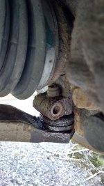
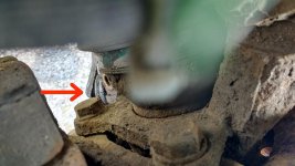
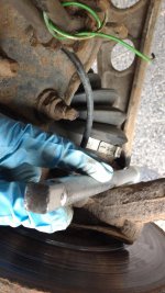
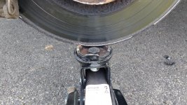
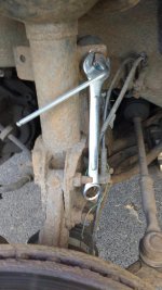
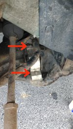
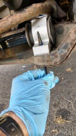
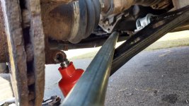
b) If not, you need to get the tip of the pin into the clamp. Here's what I did: I lay down on my side on the ground with a long 5 ft lever (1in diameter length of steel pipe from the scrapyard), one end wedged under either the subframe (OS wishbone) or a triangular bracket sticking out under the front of the gearbox (NS wishbone) (see photo), and using my bodyweight on my end of the lever, I levered the wishbone and balljoint down below the clamp, removed the plastic protective cover off the balljoint, then shoved the wheel hub and clamp over the balljoint pin, and released the lever so that the pin went into at least the mouth of the clamp. If you can get the pin in further, fine, otherwise now do step a) above.

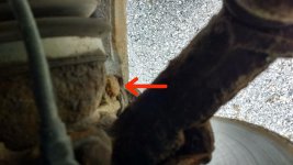
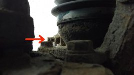
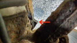
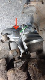
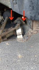
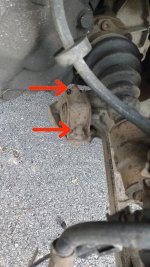
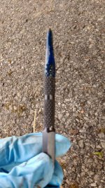
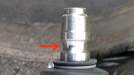
c) Once the pin is firmly inserted into the clamp, you need to manoeuvre the pin up and down to get it to the correct height. The correct height is where the semi-circular cut-out in the pin (which the pinch bolt eventually fits through) (see photo) is at the same height as the pinch bolt holes in the pinch bolt clamp.

To move the pin up the clamp: gently tap on the bottom of the balljoint with a hammer. Move the pin up gradually and keep checking for the correct height in the clamp (shine a torch through the pinch bolt hole(s), and check to see whether the pinch bolt will go through the holes). If you're too low or too high you will see the pin and/or edges of the cut-out obstructing the pinch bolt holes.

To move the pin down the clamp: either use the aforementioned lever to lever the wishbone and pin down (which is what my local garage did), or tap down on the projections either side of the wishbone balljoint as you did on disassembly.

Tip: It is better for the pin to be too low than too high, as I found it harder to move the pin down (new wishbone bushes exert a greater force upwards on the pin than old wishbone bushes), so try to start with pin low, and tap it up gradually, continually checking, to get to the correct height.

That's all the tricky bits done.

Photos:
- Levering down the wishbone
- Cut-out on balljoint pin (for pinch bolt to go through)
 

Attachments

  • 17 Levering down the wishbone.JPG
    17 Levering down the wishbone.JPG
    112.6 KB · Views: 81
  • 18 Cutout on balljoint pin.JPG
    18 Cutout on balljoint pin.JPG
    63.6 KB · Views: 34
Last edited:
Step 16: Install the pinch bolt and nut, and tighten fully:

With the balljoint pin at the correct height in the clamp, I found the pinch bolt went through the clamp holes easily *by hand*. If the height is wrong the pinch bolt won't install.

I would use a *new* pinch bolt and nut.
 
Last edited:
Back
Top