Technical Heater blower speed switch

Currently reading:
Technical Heater blower speed switch

Joined
Nov 18, 2005
Messages
269
Points
95
Location
Guildford, Surrey
Hey all, does anybody know if you can get the switches separate? I got a feeling that my switch has burnt out, but you can remove the switch from the pack itself. Took the whole thing apart and cleaned it but no difference at all. My model has the auto speed regulator and climate control. Any ideas or help is much appreciated!

Cheers :D

Kimi
 
The switch on auto is only for the climate control ecu to tell the position of the switch, the blower has PWM controller.

On the normal version the current passes through the switch, but not on auto.

If the blower goes full blast on MAX DEFROST on the rightmost dial, but not when you put the speed to 4, it could be the switch or its connections.

If it does not work on MAX DEF, it could be the connections (just some generic corroded chassis groundpoint perhaps or the panel connections), or bad climate control ecu (under dash so if you have had heatermatrix leak on top of it, it could have corroded connector) or bad PWM box.

The PWM controller box should be right next to the fan (just follow the black wire from the motor).

Just pick a part from scrappy if you can isolate the fault
 
Well, did you try the MAX DEF position on the rightmost dial (after windscreen only position)?
It should engage the AC compressor (ligh for it should go on) and put the fan on max.

If the compressor light goes on, the climatecontrol ECU should be fine.

So it is the motor or the pwm box (or their connections).
You can bypass the PWM box by grounding the black wire from the motor (it should be getting permament feed from battery positive when the ignition is on).

All models with automatic cilimate control use the same setup (not sure about OBDII ones as they might have different ECU, if they are wired to the OBD connector).

If it is the PWM box and you cannot find one (I have one HLX Weekend here on local scrappy, no idea how much they want for the control boxes, but I can ask if you want), rig this controller to the switch and to the motor (you lose the automatic speed option...): :p
http://www.ebay.co.uk/itm/111143473346
 
This post contains affiliate links which may earn a commission at no additional cost to you.
Have you checked the fusebox on the drivers kneecap?
Wiring diagrams show fuse 12 and 15 (12 powers the ecu and the blower motor so I guess its fine, 15 powers the PWM box and MAX DEF switches/other stuff so I guess it is fine too).

Image
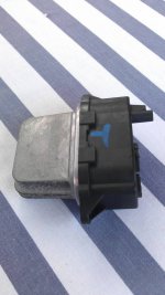
Red wire comes from fusebox (4) to the blowermotor (+), black leaves the motor to the PWM box (255), Grey wire should be power ground for the PWM box and ends up on chassis ground (222, changes color to black as other groundwires are added to the mix).

You can probe the the wires with multimeter, motor should be getting constant 12V from the fusebox, black wire from motor should also be 12V when the motor is off. Grey wire should be always gounded.


When blower should be on full, the black wire should be near 0V, when it is running but not on full blast, it might be anything depending on how good your multimeter is reading the signal (best case scenarios is that it has duty cycle function).

"It was working fine but would cut out momentarily then come back on. No matter what speed you put it on there is nothing."
So it used to oscillate but is now completely dead?
Sounds like bad ground to me, measure the grey wire when the fan switch is on full.

Use chassis ground when measuring, not cig lighter or anything that has wire running to groundpoint.

UK car so the groundpoint connections might be mirrored, sometimes not so check both sides.
 
Last edited:
Hello, having a root around this evening I found this box, is this the PWM? The terminals going into it (grey and black) were very blacked burnt, melted even. If this is it, are they easy to get hold of?
 

Attachments

  • 1377110858472.jpg
    1377110858472.jpg
    43.1 KB · Views: 57
It was inline with the blower wiring, and has heatsink to cool the FET/Transistor that does the switching, I'd say that is the thing (never seen it myself as I have had no reason to dig it up, only rebuilt the air recirculation motor near that area).

That thing is supposed to take full current passing through the blower fan so it should not melt/heat up too badly (motor shorted out? ground the grey wire from the blower and it should go full blast, it the motor starts smoking, its shorted and taken the box with it, fuse should stop it).

Best case scenario is that the terminals/crimps were loose and cooked the wires, cant say if it is repairable without proper pics of the terminals/wires.
Try cleaning the contacts on the box, clean and recrimp/solder the connectors on wires and slap it together, you got nothing to lose.

Easy to get hold of....scrappy is best choice.
Autoaircon models are easy to identify when you look at the dash.
You could look up the part number on ePer and ask the dealer, but my guess is that the price is very steep (400€ around here for the air recirculation flap motor, and that's just simple DC motor with plastic gearbox).
 
That's great, I'm currently watching one on eBay, but will see of I can source One locally. You mentioned earlier about the recirculation system, do you know where its located, only my gf caught the wire with her foot and pulled them out the end! :thumbdown:
 
Its on the side of the flap (outside, not towards the centre of car as that would be hell), some 20cm down from the hinge. A steel rod from the motor moves the flap.
Take the glovebox off, and go upside down the footwell, the headrest makes wonders on your feet.
It has connector, but the wires are just long enough for the job, so you might need to repair them while upside down, polarity only affects direction of the motor.
Battery operated soldering iron from radioshack is nice for small jobs like these.

This happened to mine:
Broken
Replacement and its ghettorigged controller
 
That's great I'll give it a go. Messaged a few people on eBay with breaking fiats and they say they have the resistor fitted but it has red and black wires rather than grey and black. Is there any difference at all?
 
Did you try cleaning the old?

It should have couple other wires (control) going into it, they matter more.
And it is not a resistor.

There should be marea workshop manuals on the downloads section, wiring diagrams are there. Looked through the marea ones (except 150 as it had no autoac diagrams) and all the wires were grey power ground, black power wire from motor, grey controlground and two control wires (power and signal is my guess).

Did the bravo/brava even come with auto ac? Ive only seen manual AC for sale and wiring diagrams had only manual AC on quick look.
 
Managed to source One second hand, so going to fit it, one problem though I don't know what wire goes to what terminal as the grey and black wire terminal melted and fell apart. Anybody able to load a picture up so I can have a look :thumbup:
 
I assume it has a N-FET inside it, so it should have builtin diode going the opposite way.
Measure with multimeter on diode range, it should conduct the other way but not the other, when nothing is connected.
Put the wires the way which it does not conduct.

I can maybe crawl in there during the weekend, but not too sure about my schedule.
 
I thought the diode check came out OK, so I did not look into it...
I should have some spare time this weekend.
 
Back
Top