

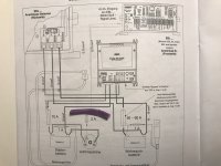
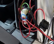
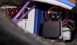
I have bought a 2021 ducato camper van and just realised that the leaisure battery is not charged when the engine is running. It is fitted with electro block EBL 119 together with a booster WA 121545. While trying to figure out if the EBL received the d+ signal I found the d+ wire for the booster squizzed underneath the seat baseplate. It has for sure made a short circuit to ground. After fixing the broken cable I still have no signal on the d+ wire at the EBL. I have gone through the fuses in the compartment fuse box with out finding any fuses blown. I can see in some wiring diagrams there should be a 2a fuse just “after” the alternator. Starter battery is charged at 13.8V.
Does any one have any clue where the d+ fuse is located?
Is there any easy way to find out if is 2A d+ fuse is blown or not? ( Engine symbol goes out on the dashboard when the engine is started.)
Does any one have any clue where the d+ fuse is located?
Is there any easy way to find out if is 2A d+ fuse is blown or not? ( Engine symbol goes out on the dashboard when the engine is started.)

")