General 1990 fiat ducato hard lights not working

Currently reading:
General 1990 fiat ducato hard lights not working

should I be removing the whole dashboard to get a look.
Sorry , i struggle being around during the week , I work some pretty strange work patterns , with very long hours . I'm a trucker by trade , and work for an agency , so my hours can be pretty indifferent . Certainly not the regular 9 to 5 of many !
This is the reason , i'm not around for long periods on the forum , and why i missed your original posting .

Now , i would strongly advise against that move at this time . They can be extremely difficult to refit , seldom actually refitting properly . Also with a dash of this age , they can become brittle , and that increases the risk of damage . I would class a dash removal as last chance saloon , when everything else has failed , so lets not think of going there , just yet .
What i would suggest , is looking for ways of getting better access though .
I think you will need to remove the steering shroud , so access can be gained to the multi-function switch behind the steering wheel . But here again be careful , it can also be brittle . It should be secured by cross headed screws from underneath , somewhere between 4 and 6 . The bottom half should remove fairly easily , but be careful with the top . Take a good look inside before you do remove the top , as you maybe able to reach what you need without removing . The tops are very nearly always difficult to remove . You will need access to the left hand stalk , and connections , plus any plugs that are hidden within .

Just as a point in fact here . On my van , the series 2 dash is in two halves . The main part or upper part is one piece and stretches right across the van . However , as i mentioned in an earlier post , it's also an A class motorhome , which is actually wider than the original van by a good 600mm . The result of which , is the dash doesn't reach from one side to the other , and should enable a complete removal relatively easy , compared to that of a standard van (In a standard van , even the width of the van itself can work against you) . Even so i've left my dash in place , and removed the lower panels instead . Now basically these are moulded in two half sections making them much easier to handle , but even this can be risky . I have already noted damage to some of the mountings , from previous removals by previous owners . However this has allowed access to the parts i need , and this is what i would advise you look for .

What i do need to know though is what type of van this is , just so i know what i'm dealing with . I get the feeling it's a straight forward standard van , is this correct or is it a converted camper ? . And if it has been converted , is it a professional or amateur conversion ? . This can mean the wiring has been mucked around with , in the past , but then a standard van probably not !

Another thing i would advise , is you to source a good quality tester . It looks like we are gonna have to do a little prodding here , and the solid tip of a proper tester will be a great aid . It may even save taking bits apart , and so lighten the work load . I still feel your problem is behind the dash and plugs will need to be tested . This could be done without separating , quite often while still in place . All part of the being gentle approach .

Now at the head of my last post , i posted an urgent warning . You have not mentioned it in your last post , so i'm gonna repeat that warning .

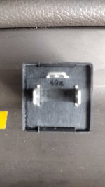
**************FUSE ONE LOOKS UNHAPPY *******************,

check it out . Your picture makes it appear to look deformed , and this could be melting , Check it out . If it is deformed in any way , SLING IT , and replace with a new one .
 
but I think that it will be more appropriate to @airwave 's vehicle.

Yes , that is a series 2 indicator system . I'm gonna try and explain this diagram a little better , mainly for the benefit of , chrissysimmo51 , who is probably looking at this and thinking , errrrrr .

Okay , now first off , on the left of the diagram , we have a long line with a rectangular box marked BB00 . Now that is the battery , following down it feeds to M47 , which basically is earth , that's the vehicle earth actually on the main chassis .
But if we follow the line up we can see it feeds up to the ignition switch (CA00) , which in turn feeds the fuse box (BF00) at position one . Now going back to the original battery line , about half way between the battery and igntion switch , it passes through another box (BB10) , this is the vehicle main fuse , and just after that there is a junction where a second wire bypasses the ignition switch , and goes direct to the fuse box , position 17 . These are the two main supply currents we've been talking about , for indicators and hazard lights , but notice the direct feed to fuse 17 does not pass through the ignition switch . This means the circuit is permanently live , ignition on or off , and is the feed for the hazard lights (remember i've already mentioned fuse 17 , is hazard lights on the s2) .

Now here is the interesting bit , notice both fuse 1 , and fuse 2 feed directly to box 2300 , this is marked as hazard warning . Now even i'm a little confused by what is meant here , because that's all it's called . I believe it's the switch , as there are a good amount of wires feeding this unit , and there is a warning light as well (the circle with a cross inside is indicating a bulb) . I have my switch remove at this time , and can confirm there are a good many wires connected to this unit . But this may be wrong , and anyway i don't claim to be perfect !
Now back to the wiring , and here is the connection between the two circuits , i was talking about and possible failure point . Fuse 1 supplies terminal 2 on component 2300 , and feeds inside to the notation for a switch in the closed position , this completes a circuit between terminal 2 , and terminal 1 allowing power to component 2305 , which is the flasher relay . Now go back to fuse 17 , this leads to terminal 3 of component 2300 and directly to an open terminal on the same notation for a switch , but this time it can't go any further , as it's whats called an open circuit . The switch notation has to be moved to the lower position to allow power to flow , and in doing so opens the circuit from fuse 1 . This further reinforces my opinion this is the switch , as it's a push to make switch . But notice the right side of that box , there are another 3 open circuits that connect to actual systems like exterior lights (2320 , 2340 , 2345 , 2325 , 2630 , and 2635) , internal warning lights (0004) , and probably more importantly the direction indicator switch (2001) itself .

The remaining third of the diagram is basically outside flashers , and repeaters . 2630 , and 2635 are the rear light clusters , but only the wiring is shown for the indicators , notice again the individual bulb markings .

Now i have mentioned the hazard warning switch itself is the failure , but note i also used the word possible ? . I'm gonna stick my neck out here and say this is the likely failure point , as this is the one point where both circuits come together . But lets not forget , this is a series 2 wiring diagram , so don't dash out and source one just yet , these things are quite expensive , and i don't want you spending unnecessary money . A point that does bug me , is why has it failed right at this minute . Yes it could be old age , i have actually replaced all my main switches because of this . It would also account for the original fuse failure at the same time , but was there something else at play here . We need to confirm the failure , then replace if necessary .
 
@airwave ,

Please see the two line post #1 in this thread, wherein the OP clearly states that he has changed the hazard light switch, and flasher unit.

Given that both the switch and flasher have been changed, I suspect a wiring fault. I have requested the flasher rating, so that we will know that a single flasher unit will support both hazard warning, and direction indicators.

We both agree that @chrissysimmo51 should equip himself with a 12V test lamp. I waiting to be informed that he has the test lamp, and for him to supply, if possible, the flasher rating.
 
@chrissysimmo51,

My apologies for unintentionally misleading you. My remark about the location of the relay location in my formerly owned Talbot Express, was meant as a comment on the difference between two vehicles of identical? age. The Talbot Express marque was a rebadge of the Peugeot J5.

From your photo, I think that you have found all of the relays that there are to be found. Please do not dismantle the vehicle in the abscence of further evidence.

Yes the attachment does appear to be missing. Sorry for the omission. I will add it to this post, but I think that it will be more appropriate to @airwave 's vehicle.

As an aid to resolving the 1/2 flasher module question on your vehicle, could you inspect old flasher unit for any rating. I have a Lucas 19FL FLASHER to hand it has the marking 0290, which I think means that it is contemporary with your vehicle. The rating is "12V.42/98W", so has your something like that on it. The 42 will mean a minimum of two indicator bulbs, and the 98 suggests that it would be OK with 4 off 21W indicator bulbs plus any side repeater indicators. If yours has similar markings, then only one flasher would be required.
Just a quickie for you to consider. Had similar problem with my fiat Ducati swift sundance. No indicators fuel guage or water temp all on same fuse. Replaced fuse, with fuse from old pack, ok for 30 mins then blew again. New fuses purchased put one in, no probs since after at least ,5 hours use. Nothing done to vehicle so can only think faulty old fuses but new fuses ok. Certainly worth trying
 
Please see the two line post #1 in this thread, wherein the OP clearly states that he has changed the hazard light switch, and flasher unit.

Good spot me ole mucker , i forgot that bit .

Trouble is , we have two functions out at the same time , so my feeling is it must be something common to both circuits , which in light of what you have just reminded me , is now pointing to an earth . It's starting to come full circle , and back to my original thoughts again . The saving grace is , it must be under the dash somewhere , so can't be what i found .

The main point of my post , was to try and make that diagram a little easier to understand , as there was not a key to show what different parts were . I'm not perfect , and even i struggle at times , but for someone not used to a circuit diagram it's almost meaningless , and vehicle wiring is getting more difficult every day .
I'm glad you're backing me here though , at least you've had one of these vans , mine is 10 years newer , and a different series . Jump in , if you have any thoughts , yeah .

A test lamp is much easier to use for a non electrical minded person to master . If there's current , the lamp lights , if not , you get nothing . A multi meter will give better readings , but can be more difficult to use , than finding the fault in the first place . It takes time to learn , and get the best outta the thing . This appears to have been going on too long now .
 
Just a quickie for you to consider. Had similar problem with my fiat ducato swift sundance. No indicators fuel guage or water temp all on same fuse. Replaced fuse, with fuse from old pack, ok for 30 mins then blew again. New fuses purchased put one in, no probs since after at least ,5 hours use. Nothing done to vehicle so can only think faulty old fuses but new fuses ok. Certainly worth trying

Yes mate , i had considered that . However in this case , there is a partial function . Only the indicators and hazards are non-functional . The wipers and fuel gauge , which are also on the same fuse , are working .

But you're quite correct with the comments about fuses , i've been caught the same . Bulbs can also do this . Old fuses do blow for no other reason than age , but generally there is a reason , thanks for your thoughts ..
 
Hi folks thanks for the info. I'm gonna look at the old and new relays when I can and let you know. Also get a test lamp. I've also been in contact with a auto electrician local to me and have quoted £114 to diagnose and hopefully fix the problem but will still have look myself first.
 
Hi , photos attached of the relays. The silver cylinder one is the new relay and the black cubed one is the old one
 

Attachments

  • IMG_20230621_190352029_HDR.jpg
    IMG_20230621_190352029_HDR.jpg
    1,002 KB · Views: 28
  • IMG_20230621_190345279_HDR.jpg
    IMG_20230621_190345279_HDR.jpg
    1.4 MB · Views: 27
  • IMG_20230621_190306454_HDR.jpg
    IMG_20230621_190306454_HDR.jpg
    2.4 MB · Views: 32
  • IMG_20230621_190229663.jpg
    IMG_20230621_190229663.jpg
    1 MB · Views: 26
  • IMG_20230621_190205653.jpg
    IMG_20230621_190205653.jpg
    1.1 MB · Views: 25
  • IMG_20230621_190136545.jpg
    IMG_20230621_190136545.jpg
    1.1 MB · Views: 26
Hi , photos attached of the relays. The silver cylinder one is the new relay and the black cubed one is the old one
The new cylindrical unit is rated at 4 x 21W (bulbs) or 84W maximum. The old black cuboid is able to supply 4 x 21W bubs + 2 x 5W side indicator repeaters (if fitted). The old one is the higher specification unit. KEEP IT!

Both units will support 4 off hazard flashers, but the new one is not fully adequate if you have side repeater indicator lamps.

I am now able to speculate as to a schematic diagram for the hazard flashers and direction indicators. How they are actually connected, and where the wires go, as would be shown on a wiring diagram, is another matter.

To clarify, a schematic diagram shows you how a circuit functions, while the wiring diagram shows where the connections are made. For an illustration look at the German x230 direction indicator diagram attached previously. The LHS is the schematic, and the RHS is the corresponding wiring diagram.

When you have your test lamp, I can think of two quick tests, which should help to home in on the fault, but as airwave has suggested it may involve some wire tracing, as we do not have a wiring diagram.
Ok thanks. Firstly should I get another relay exactly the same as the black one and what are the tests I need to try
 
Do not purchase new flasher relay, as old one may be OK.

I will provide more detail about tests sometime tomorrow.

Preparatory work. Find an accesible earth/chassis connection point on dash, but near fuses, so that you can connect your test lamp to chassis. I have used a spare cheap style cigarette lighter plug, to allow connection to either 12V +ve, or earth. Also prepare to access rear of hazard switch.
 
Back
Top