Technical Heater fan not working

Currently reading:
Technical Heater fan not working

siwilks200

New member
Joined
Sep 17, 2015
Messages
95
Points
27
i I'm new here.

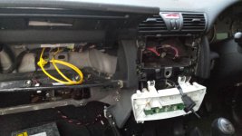
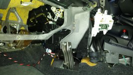
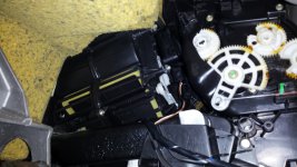
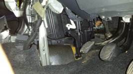
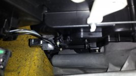
Bought a stilo few weeks back and the fan for the internal heater has always been weak...but now it has stopped working.

Sometimes after a 10min drive it willwork weak again but when I start the car again it won't.

Any suggestions please..thanks
 
I have a similar problem.

It's either the pollen filter being clogged, the motor failing, or a dodgy wiring loom.

Given that mine has worked intermittently, I suspect a failing wiring loom.

Can anyone point us too where the wiring runs are?
 
OK I've made a lot of progress today, but not fixed it.

I removed all the relevant panels to get to the blower and loom. Investigated the loom connections for signs of burns or deterioration and found nothing obvious!

So I cleaned the connections with contact cleaner which didn't work.

Also changed the main control panel heater switch for 2 different ones from the scrappy, which didn't work, not that I expected it to.

The control panel has 3 buttons for AC, demister and air recirculation. The AC and rear demister have relays that work (click) fine, the third being the air recirculation button - this works fine too from within the blower (?) as I can hear it turning the redirection blades or whatever.

Also checked my pollen filter....which I found I didn't actually have one installed!!! I guess not having one has not killed the system, just given the occupants dirtier air?!

So I'm at a loss - I can see the whole loom and connections without signs of damage. The only thing I can think of now is the resistor or blower, which is a real problem to get to, but I guess I have no other choice now but to change them....

Please help!
 

Attachments

  • 20150919_191357.jpg
    20150919_191357.jpg
    1.8 MB · Views: 405
  • 20150919_191432.jpg
    20150919_191432.jpg
    2.4 MB · Views: 335
  • 20150919_191514.jpg
    20150919_191514.jpg
    1.8 MB · Views: 295
  • 20150919_191637.jpg
    20150919_191637.jpg
    2.1 MB · Views: 313
  • 20150919_191952.jpg
    20150919_191952.jpg
    1.5 MB · Views: 274
Ive found the stilo looms tend to be crappy, if you solder or chocolate block the connections rather than rely on the fiat looms, that fixes things. Or at least it did with the airbag warning lights on mine.
 
im afraid i dont know what to do with "solder or chocolate block the connections"

i may just try replacing the heater blower if i cant work out how to find a dodgy connection with my multimeter.....

thanks
 
ahha, that sound easy enough, especially to chocolate block them...i found out what that is now!

apart from the fact that the switch connects straight back to the resistor pack - so i cant see how to solder/block them :

switch terminals > plug > wires > plug > resistor pack terminals

so i cant solder/block the wires to anything either side....unless i do it to the flat terminals which sounds silly??

cheers
 
sorry for a repeat comment below ive just made on an old thread - not sure if itll get the attention

-------------

I have removed my resistor pack - how do i test it with my multimeter?

what do i set it onto? 2000 ohms or 200 ohms, which way around and what value am i looking for?

if i can prove the resistor is faulty i can solder a new one on myself if i can choose the correct one!

can the resistor pack go instead/as well as the resistor?

many thanks
____________
 
If the resistor pack was faulty, the fan would still work normally on speed 4. Only speeds 1, 2 and 3 use the resistor pack as can be seen in the wiring diagram below. O30 is the resistor pack, H81 is the 4 position fan switch, N85 is the fan motor.

If you want to measure the resistances of the pack, measure between pins 1 & 2, 2 & 3 and 3 & 4. If working, they will be very low values, probably between 0.5Ω and 2Ω. You will need the multimeter on its lowest Ohms scale (probably 20Ω or 200Ω). There are no semiconductors in the pack, so it doesn't matter which way round you connect the multimeter leads.

The resistors are high wattage wire-wound resistors, embedded in a ceramic coating. You will not be able to replace them individually. If the pack is faulty, get a new, or known good replacement. The small component on the end of the pack is a thermal fuse.

Assume you've already tested fuse F31 in the dashboard fuse box (B2), and fuse F8 and relay T8 in the engine compartment fuse box (B1).
.
 

Attachments

  • Heater Wiring.JPG
    Heater Wiring.JPG
    78.1 KB · Views: 231
  • Heater Fan Resistor.jpg
    Heater Fan Resistor.jpg
    87.7 KB · Views: 90
Last edited:
Excellent reply...thanks!

Tested the resistor pack as u describe and I get readings between 0.7 and 1.2 so I guess it's ok. Do I need to check the thermal fuse?

I haven't checked the engine compartment fuse or relay so that's next!

How do I check the relay? Thanks
 
The thermal fuse is shown on the resistor pack circuit diagram as a "T" in a circle. Therefore, if you have continuity between pin 1 and any of the other pins, the fuse is OK.

The fan should have a 12v +ve supply whenever the ignition is switched on. With the ignition switched on, check for 12v +ve at pin 2 of the fan motor. According to the wiring diagram, it should be a light blue wire (shown as A), but colours on the wiring diagrams are sometimes wrong. If you have 12v +ve at pin 2 of the fan motor, then fuses F31, F8 and relay T8 should be OK.
.
 
how do i tell which is pin 1? the pins arent labelled and i cant tell from comparing it to the diagram.

the reading however from one side of the thermal fuse to the other is 0.3 at best (i expected 0.00 for the best continuity) but its a bit old and discoloured) and between none of the pins as you described earlier do i get a break (1) like in a busted fuse

so it sounds like the whole thing is ok? thanks again for helping!

do i need to be concerned with the +ve part (whatever that is!) of the testing of the 12v supply?
 
Last edited:
every now and then it works even though poorly compared to my other cars

After a brisk drive it is now working as poorly as ever without the resistor installed....obviously just on setting four.

but I swear it will not work tomorrow morning and probably for another couple of days before it randomly turns back on

does this help narrow down the diagnosis
 
Last edited:
cheers dude - please excuse my ignorance... ..

if only i knew how to do that - i have lots of equipment / wiring and know how but need to know specifics of what terminal on the battery, using what, and where to connect to.....to test the motor

if i didnt ask right now, id envisage you mean the red positive from the battery and black earth, using thick wire from somewhere (?) all the way to my motor - then to connect the red positive from the battery to the positive (blue?) of the 12v supply to the rear of the motor, and the earth from the battery to the (brown?) - it should work on touch...without turning the ignition i presume


By wire I mean I have speaker wire...which may be underrated to use? Don't wanna shock!


do you mean to remove the battery and take it nearer to the motor, for ease of connecting smaller length wires?

id really like to know how to do this and dont want to make it worse and im sure others would like a step by step?!

thanks again
 
Last edited:
I have now tested the engine compartment fuse and relay and they are both fine relay reads about 70

but I presume the relay and fuse would have been ok anyway because every now and then the blower comes on
 
I've put the resistor back in a time when the blower was working and it works ok changing the speed for 4 options
 
woooo i finally go the fan out and tested it using speaker wire to the battery and it works fine!

er.... am i testing it right?

so i guess my problem lies elsewhere...maybe the wiring loom or connections?

can someone recommend how to test the connections?
 
Back
Top