Again, added to FF.
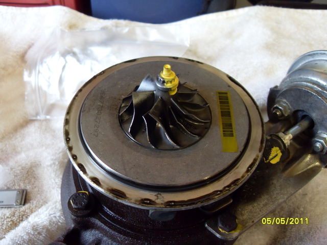
This is where the turbo description comes from i.e. gt1749v and also what may or can be changed to make a hybrid.
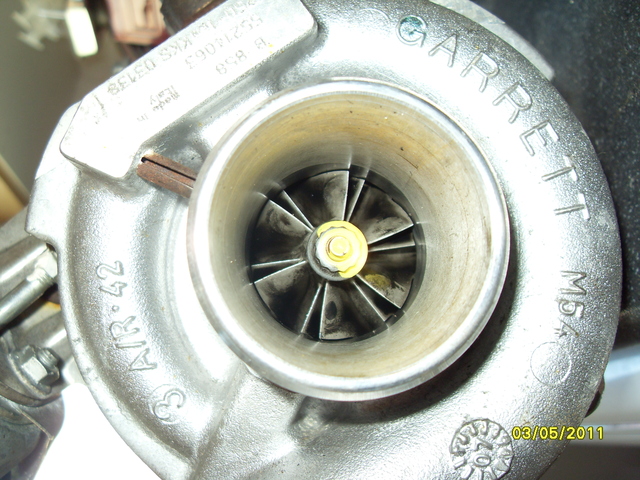
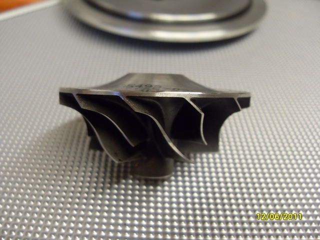
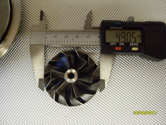
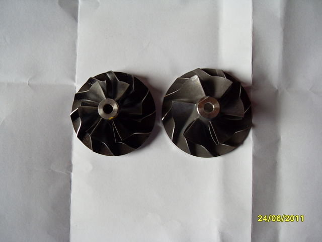
49=compressor exducer = 49mm
Compressor inducer diameter whatevers spec'd( gives trim).
(48 trim)smaller = more responsive , (60 trim)larger = more flow top end (possibility surge low end)
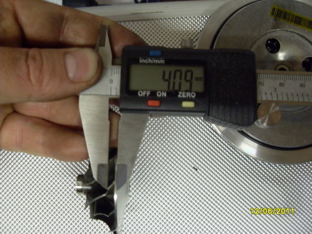
Compressor wheel will also be spec'd for tip height e.g. 4.0mm
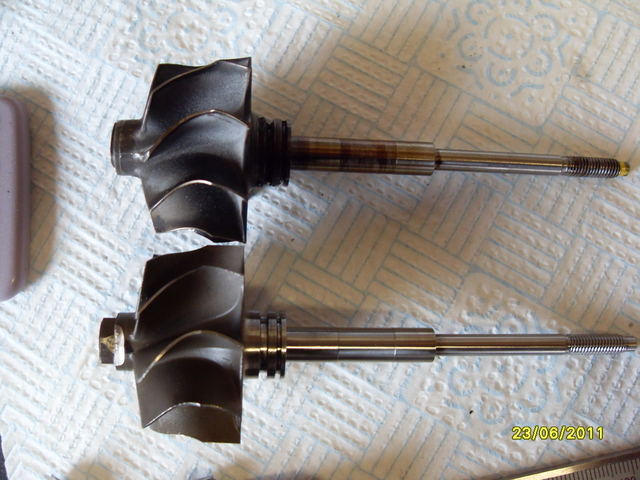
A different wheels may vary in overall length and back design.
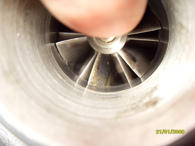
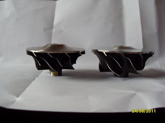
This is comparison between a 49mm 34.6mm wheel and a 52mm 38.6mm wheel
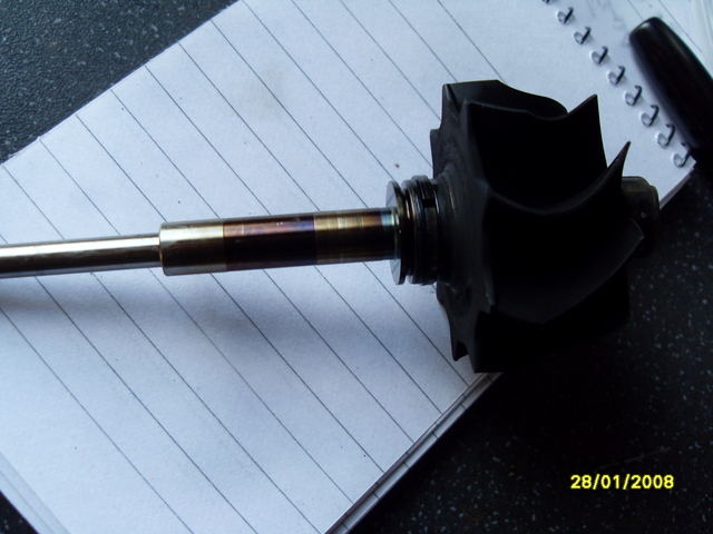
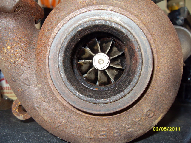
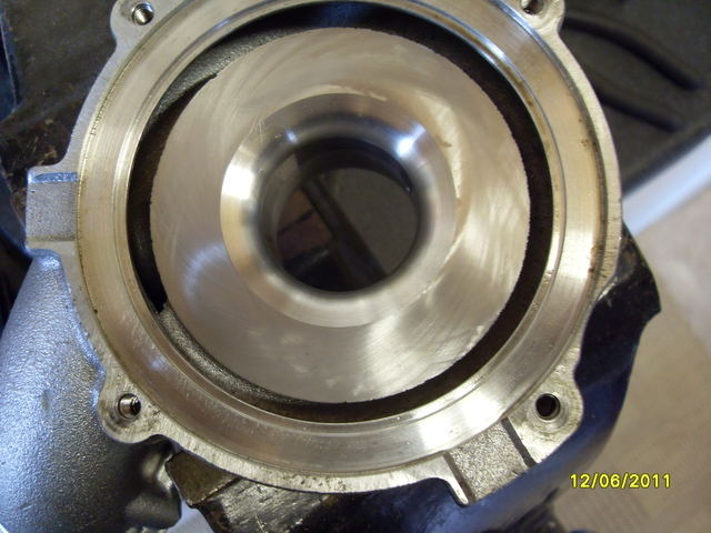
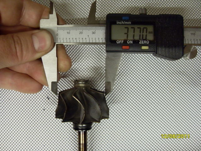
The turbine side gives the gt17 usually called frame size, once again several 17 turbines will have different dimentions.
This one has a 43mm inducer(largest diameter , inlet to tubine) and a 37.7mm exducer or outlet.
A smaller exducer will make more responsive but restrictive to flow top end, a larger exducer will make better flow top end but laggier bottom end.
Your max bhp is usually restricted to the max flow from the turbine side wheel/housing.
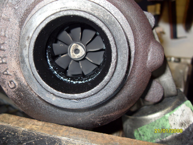
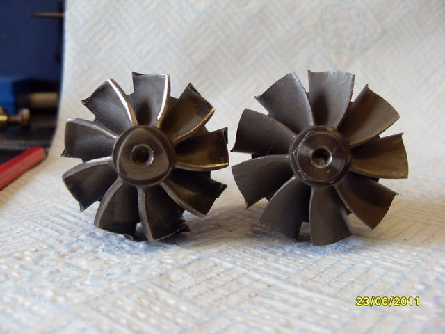
Heres a 17 turbine with larger exducer (more flow but possibly more lag).
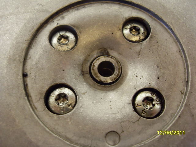
Also to consider are housing a/r values also limiting flow characteristics.


")