

You are using an out of date browser. It may not display this or other websites correctly.
You should upgrade or use an alternative browser.
You should upgrade or use an alternative browser.
Technical How to make a OCS sensor
- Thread starter gsc1ugs
- Start date
Currently reading:
Technical How to make a OCS sensor
Hi
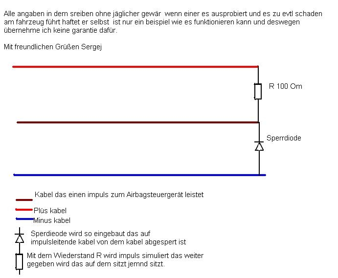
How do i make this device? please see from the link below, i have the resistor and diode just wondered what goes where?
What link below.

Maybe this will help ...
anyone speak german?
I just typed it into Google Translator, Didn't make much sence. :shrug:
yes that is what the drawign is describing....a VERY simple circuit to replace something that is quite complex....another one ive seen on the forum is:
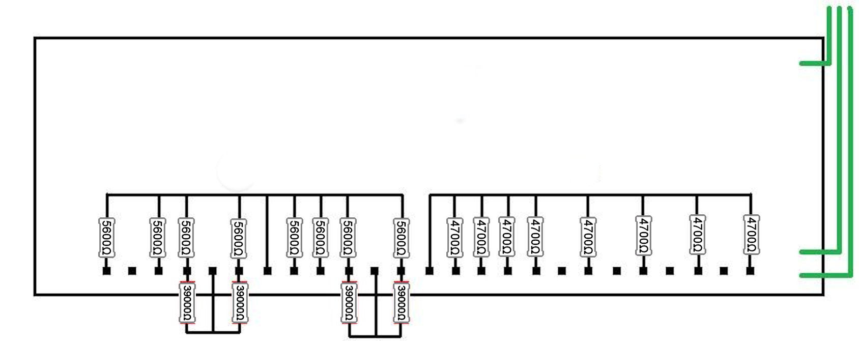
but im not quite sure how you'd make it, as there seems to be a bit missing...
but im not quite sure how you'd make it, as there seems to be a bit missing...
Last edited:
Here's another.
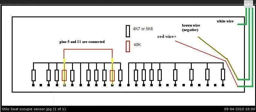
All seems very messy to me.
Would it not be better to install one of these?

This emulator emulates signal of occupied passenger seat recognition sensor for FIAT Stilo.
Emulator shows that passenger seat is always occupied and airbags will deploy in the case of collision. Easy to install: You must connect only 3 wires, seat disassembling and faults erasing not needed.
http://cgi.ebay.co.uk/Airbag-Occupancy-Sensor-Emulator-Fiat-Stilo-/180664069766
All seems very messy to me.
Would it not be better to install one of these?
This emulator emulates signal of occupied passenger seat recognition sensor for FIAT Stilo.
Emulator shows that passenger seat is always occupied and airbags will deploy in the case of collision. Easy to install: You must connect only 3 wires, seat disassembling and faults erasing not needed.
http://cgi.ebay.co.uk/Airbag-Occupancy-Sensor-Emulator-Fiat-Stilo-/180664069766
Last edited:
This post contains affiliate links which may earn a commission at no additional cost to you.

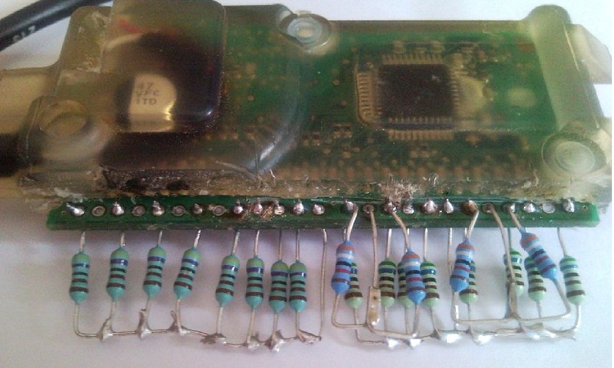
Ive tried this, it dont work, will post diagram of my made up ocs tell me if im wrong
Post up a photo of your actual solution so we can see what and how you did it?
Last edited:
i highly doubt that a single diode and resistor will replicate what the airbag ecu needs to see....id forget that design for a start. either consider making one of the more complex ones or buy the emulator from ebay
:yeahthat:
aaronsummerhayes
New member
All that german at the top basically says is he takes no responsibility if you balls it up and break yr vehicle.
Bottom bit for cable labels is pretty obvious
I found these. Not had money to buy one yet tho...
CLICKY FOR EBAY LINK
Bottom bit for cable labels is pretty obvious
I found these. Not had money to buy one yet tho...
CLICKY FOR EBAY LINK
This post contains affiliate links which may earn a commission at no additional cost to you.

Did you fit the diode the correct way? Can't see the marking on it.