Hi all,
I just bought an abarth leather steering wheel minus the paddles, im going to fit it to my 1.8 dynamic.
As some of you may know, i dont have a "conventional" setup, im running a carPC, i want to link the steering wheel buttons to the carpc.
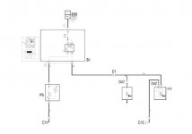
my understanding is that there are three types (in general) of steering wheel buttons:
1) simple button push presents a voltage on the end of a wire
2) all the buttons are on a voltage divider network and pressing a button changes the resistance presented
3) steering wheel buttons on a bus
im hoping its option 1 in the stilo, because thats the easiest one to interface into a PC, but i fear it could be option 3....
also, if ive gotten rid of the OEM stereo and i dont have a connect nav, will the steering wheel have any "normal" use in the car?
thanks for any help")
I just bought an abarth leather steering wheel minus the paddles, im going to fit it to my 1.8 dynamic.
As some of you may know, i dont have a "conventional" setup, im running a carPC, i want to link the steering wheel buttons to the carpc.
my understanding is that there are three types (in general) of steering wheel buttons:
1) simple button push presents a voltage on the end of a wire
2) all the buttons are on a voltage divider network and pressing a button changes the resistance presented
3) steering wheel buttons on a bus
im hoping its option 1 in the stilo, because thats the easiest one to interface into a PC, but i fear it could be option 3....
also, if ive gotten rid of the OEM stereo and i dont have a connect nav, will the steering wheel have any "normal" use in the car?
thanks for any help