

Guide: Panda 169
Fitting and wiring fog lamps using accessory switch and independent relay
Difficulty 3 / 4 Soldering required
Time to do ½ a day

Panda 169 without fog lamps can be fitted quite easily.
Tools and materials required.
Large flat screwdriver / pry tool and a thick cloth or chamois leather
10mm spanner
Wire strippers
Volt meter
Small screw driver
Terminal crimping tool
Sewing Needle
Razor blade / Stanley knife
Good sized Philips screw driver
2 large penny washers small hole size. 2 Stainless self tapper screws
soldering iron and flux core solder and flux for preference
Lamp connector plugs (eBay)
Fog lights and fog lamp surrounds for the bumper.
Cable ties and insulation tape
Heat-shrink insulation
Two in line fuse holders
20A spade type fuse (LED fuses are highly recommended LED lights if the fuse is blown – bloody magic!!)
5A spade type fuse
1 12v 4 terminal relay
Drill and 2mm high speed bit
Small self tapping screw
12v Wire preferably 2 colours 10A capacity.
Quite a large supply of patience…….

Overview
For novices, wiring is simple. It just requires a circuit from positive to accessory to negative. On modern cars negative is the earth as well. Modern cars are thus known as negative earth.
Power must come from a live / positive supply. It goes through a fuse, which must be fitted as near as possible to the + positive connection point and through a supply wire via a switch to the accessory. In this case fog lights.
Its essential for safety
These plugs are nearly there but require the pins to be bent slightly to make contact with the socket as the supplied pins were slightly to small.

Fitting
Start by installing the relay. Decide on the location. This needs access to install the wires and clearance from any other bodywork. You need to be able to drill a fixing hole in a suitable panel and to do this without drilling into anything that is behind the hole!! The relay must be clear of any water drainage too. (See Pic) Fix the relay but only tighten the screw gently as it will need to come out again for fitting the wires. I used the bulkhead alongside the brake servo.

Note here relay location and the two wires to the switch passing through the bulkhead grommet top left of photo. The fused red wire runs from a spare connection on the + positive terminal of the battery to the high current supply to the relay. Use a 20A fuse.
Installing the wires. Use cable rated at 10A. Cut the wires to length so they can be put loosely into place, and so you can fit the lamp unit plugs to your live (+) wires. Leave a good amount of slack to allow for routing the wires neatly. Slack can be trimmed at the relay, battery and switch to leave a neat finish. Leave an extra 30cm on both wires behind the fog light grilles to allow for bumper removal if needed in future.

I route through the fuse box as the wires can then be most easily tied to the existing wiring harness for security and tidiness.
The supply live (+) wires start behind the fog light positions and go through the front panel into the engine bay and up near the fuse box to the relay. The left side is a straight run, the right side runs across under the radiator to the left side and up alongside the left side wire to the relay. To make it easier, use one colour wire for + live wires and a second colour for the – wires. I use a printed label to identify left and right wires for subsequent maintenance. Bring the top ends of the two live supply) wires that you installed to the fogs, together at the relay, trim to length and solder them both to a single female connector.

New wires brought together under the radiator and tied to existing harness on their way to the relay.
Next install the earth wires. Run the left side earth from the light (plus 30cm to the battery negative terminal. I earthed the right side fog light to the body using the clutch fluid reservoir fixing bolt. Fix a crimped eyelet on each wire. I ALWAYS solder the crimped terminals to avoid any possibility of the crimped wires becoming detached and causing short circuits / fire. Both the battery earth terminal and the clutch fluid reservoir are 10mm size.
Tidy the wires and cable tie them into place so they cannot become entangled with other components such as the fan blades.

Earth point for right side lamp. Red item in pic is non-standard crankcase breather catch can. Clutch fluid reservoir bottom left corner
Install the fog lights into the new plastic surrounds and fix with the supplied screws or use self tappers as required, from memory three short screws from the back and one long one about 4cm from the front. Use of a proper star head / Torx head screw is recommended as they are tight to remove subsequently

Next you need to install the plug at the fog lamp end of the wires. This is by far the most taxing part of the job! Remove the bulb covers from the lamps and look to see which pin is the earth and which the live wire so the plug can be correctly aligned. Solder the two wires to the pins and assemble the plug with the waterproof seals. I found the plugs from eBay are not a perfect fit and needed to support the wires to prevent them from working loose. I used a hot glue gun to create a rigid section of wire from the plug sufficient to allow it to be tied up and stop this problem. Encapsulating the wires in a layer of hot glue produced a rigid section that enabled a solid fixing. The plugs have settled over time and now remain secure. Install the bulbs into the fog lamps fit the covers and plug in the wires. To ensure that the lights were waterproof I further covered the backs of the wiring plugs with silicon mastic. I also applied silicon grease to the lamp rear seals.
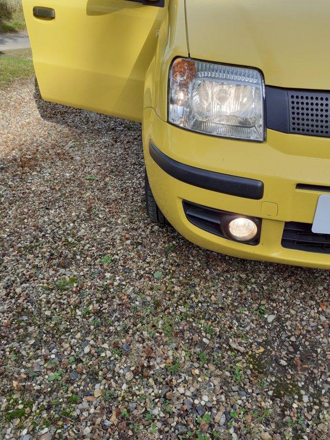
You can now test that the lights work by holding the positive feed wire connector to the battery positive terminal at which point they should light up. Trouble shoot any connections until the lights work before installing into the bumper.
Fitting light surrounds
Remove the fixing screw(s) and pry out the blanking plates from the bumper, Use the cloth or a chamois leather to prevent paintwork damage. Install the new foglamp holders in their surrounds into the bumper. It is awkward feeding these into the hole and getting them sitting correctly in the bumper but it can be done with patience. When you have the lamp and its holder in the right place its immediately obvious. You will then need to fix these in place with two screws through from under the bumper using the penny washers to provide the support needed. The holes needed for these screws are predrilled as is the access hole for adjustment. Adjustment can be done using a ¼” drive socket (8mm) and extension bar from below.
Fitting the relay and switch
The relay has a low current side and a high current side. Low current wires (signal wires) are used to supply the relay switch, which switches the high current wire that supply the lights. I took the low current power or signal from the side lamp wire at the back of the left headlamp. This ensures the fog lights will turn off when the ignition is tuned off at the key and if the lights are turned off, exactly as the headlamps and factory fitted lights. The current draw to power the relay does not affect the can bus system. When the side lights are on power flows via the switch to the relay. The fog light switch activates the relay which takes power direct from the battery to the fog lights.

The wire connected to the side lamp bulb live feed at the rear of the left hand headlight is fused and is on its way through the bulkhead to the switch inside the car. The 20A fuse shown is for test connections and was replaced by a 5A fuse on completion, The connection was made by splicing into the side lamp live wire and soldering the connection. Heatshrink was used and tape added to support the wiring. The three wires adjacent are the high current wires (blue) and the left lights earth (green)
There are only four connections.
Once the wires are connected to the relay tighten the fixing screw securely. Especially important if using this screw for the relay earth wire,
I pondered (Panda’ed??) using a factory fog light switch. This is not really viable as the switch comes in a block with hazard lights etc. These switches plug into the factory wiring socket directly, and there isn’t one. Also, there is no access the getany wires to the factory switch even if you have one. It simply wouldn’t be possible. So I looked for an alternative place and could only find one spot that wouldn’t cause a huge amount of work. This is adjacent to the cigarette lighter / accessory socket. The plastic plate can be levered up from the front or rear two tabs to release, one each side - with a small screw driver- and there is just enough space to fit a suitable switch. I used a Ring push on / push off switch with built in warning light. The switch is fragile and need gentle handling. The crimped connections are smaller size!!
Earth point was a single hole under the socket and a self-tapping screw.


Once the switch wires are installed under the central part of the fascia and brought through connection is straight forward. One wire to the switch comes directly from the side light connection seen above. The return wire requires another crimped terminal and connection to the relay. Install fuses into the two fuse holders and test that the lights now work with the switch. Reinstall the socket plate and the job is complete.
Wiring this way allows the fog lights to be used independently of the headlights and they will always switch off when the key is turned off and removed.
Wiring diagram Apologies for the freehand

Panda Nut Worldwide Inc. copyright not reserved by order of HM The Panda Nut myself. P.S. My proofreader says I am a Nut!
Please use with caution as guidance only.
This guide should be applicable to any car where independent wiring and switch are used.
Fitting and wiring fog lamps using accessory switch and independent relay
Difficulty 3 / 4 Soldering required
Time to do ½ a day
Panda 169 without fog lamps can be fitted quite easily.
Tools and materials required.
Large flat screwdriver / pry tool and a thick cloth or chamois leather
10mm spanner
Wire strippers
Volt meter
Small screw driver
Terminal crimping tool
Sewing Needle
Razor blade / Stanley knife
Good sized Philips screw driver
2 large penny washers small hole size. 2 Stainless self tapper screws
soldering iron and flux core solder and flux for preference
Lamp connector plugs (eBay)
Fog lights and fog lamp surrounds for the bumper.
Cable ties and insulation tape
Heat-shrink insulation
Two in line fuse holders
20A spade type fuse (LED fuses are highly recommended LED lights if the fuse is blown – bloody magic!!)
5A spade type fuse
1 12v 4 terminal relay
Drill and 2mm high speed bit
Small self tapping screw
12v Wire preferably 2 colours 10A capacity.
Quite a large supply of patience…….
Overview
For novices, wiring is simple. It just requires a circuit from positive to accessory to negative. On modern cars negative is the earth as well. Modern cars are thus known as negative earth.
Power must come from a live / positive supply. It goes through a fuse, which must be fitted as near as possible to the + positive connection point and through a supply wire via a switch to the accessory. In this case fog lights.
Its essential for safety
- correctly rated fuses are fitted at the nearest possible place to the source of power when a wire is installed
- All connections are totally secure to avoid short circuits
- Wires are routed so they cannot become caught in moving parts of the engine. Use cable ties.
These plugs are nearly there but require the pins to be bent slightly to make contact with the socket as the supplied pins were slightly to small.
Fitting
Start by installing the relay. Decide on the location. This needs access to install the wires and clearance from any other bodywork. You need to be able to drill a fixing hole in a suitable panel and to do this without drilling into anything that is behind the hole!! The relay must be clear of any water drainage too. (See Pic) Fix the relay but only tighten the screw gently as it will need to come out again for fitting the wires. I used the bulkhead alongside the brake servo.
Note here relay location and the two wires to the switch passing through the bulkhead grommet top left of photo. The fused red wire runs from a spare connection on the + positive terminal of the battery to the high current supply to the relay. Use a 20A fuse.
Installing the wires. Use cable rated at 10A. Cut the wires to length so they can be put loosely into place, and so you can fit the lamp unit plugs to your live (+) wires. Leave a good amount of slack to allow for routing the wires neatly. Slack can be trimmed at the relay, battery and switch to leave a neat finish. Leave an extra 30cm on both wires behind the fog light grilles to allow for bumper removal if needed in future.
I route through the fuse box as the wires can then be most easily tied to the existing wiring harness for security and tidiness.
The supply live (+) wires start behind the fog light positions and go through the front panel into the engine bay and up near the fuse box to the relay. The left side is a straight run, the right side runs across under the radiator to the left side and up alongside the left side wire to the relay. To make it easier, use one colour wire for + live wires and a second colour for the – wires. I use a printed label to identify left and right wires for subsequent maintenance. Bring the top ends of the two live supply) wires that you installed to the fogs, together at the relay, trim to length and solder them both to a single female connector.
New wires brought together under the radiator and tied to existing harness on their way to the relay.
Next install the earth wires. Run the left side earth from the light (plus 30cm to the battery negative terminal. I earthed the right side fog light to the body using the clutch fluid reservoir fixing bolt. Fix a crimped eyelet on each wire. I ALWAYS solder the crimped terminals to avoid any possibility of the crimped wires becoming detached and causing short circuits / fire. Both the battery earth terminal and the clutch fluid reservoir are 10mm size.
Tidy the wires and cable tie them into place so they cannot become entangled with other components such as the fan blades.
Earth point for right side lamp. Red item in pic is non-standard crankcase breather catch can. Clutch fluid reservoir bottom left corner
Install the fog lights into the new plastic surrounds and fix with the supplied screws or use self tappers as required, from memory three short screws from the back and one long one about 4cm from the front. Use of a proper star head / Torx head screw is recommended as they are tight to remove subsequently
Next you need to install the plug at the fog lamp end of the wires. This is by far the most taxing part of the job! Remove the bulb covers from the lamps and look to see which pin is the earth and which the live wire so the plug can be correctly aligned. Solder the two wires to the pins and assemble the plug with the waterproof seals. I found the plugs from eBay are not a perfect fit and needed to support the wires to prevent them from working loose. I used a hot glue gun to create a rigid section of wire from the plug sufficient to allow it to be tied up and stop this problem. Encapsulating the wires in a layer of hot glue produced a rigid section that enabled a solid fixing. The plugs have settled over time and now remain secure. Install the bulbs into the fog lamps fit the covers and plug in the wires. To ensure that the lights were waterproof I further covered the backs of the wiring plugs with silicon mastic. I also applied silicon grease to the lamp rear seals.
You can now test that the lights work by holding the positive feed wire connector to the battery positive terminal at which point they should light up. Trouble shoot any connections until the lights work before installing into the bumper.
Fitting light surrounds
Remove the fixing screw(s) and pry out the blanking plates from the bumper, Use the cloth or a chamois leather to prevent paintwork damage. Install the new foglamp holders in their surrounds into the bumper. It is awkward feeding these into the hole and getting them sitting correctly in the bumper but it can be done with patience. When you have the lamp and its holder in the right place its immediately obvious. You will then need to fix these in place with two screws through from under the bumper using the penny washers to provide the support needed. The holes needed for these screws are predrilled as is the access hole for adjustment. Adjustment can be done using a ¼” drive socket (8mm) and extension bar from below.
Fitting the relay and switch
The relay has a low current side and a high current side. Low current wires (signal wires) are used to supply the relay switch, which switches the high current wire that supply the lights. I took the low current power or signal from the side lamp wire at the back of the left headlamp. This ensures the fog lights will turn off when the ignition is tuned off at the key and if the lights are turned off, exactly as the headlamps and factory fitted lights. The current draw to power the relay does not affect the can bus system. When the side lights are on power flows via the switch to the relay. The fog light switch activates the relay which takes power direct from the battery to the fog lights.
The wire connected to the side lamp bulb live feed at the rear of the left hand headlight is fused and is on its way through the bulkhead to the switch inside the car. The 20A fuse shown is for test connections and was replaced by a 5A fuse on completion, The connection was made by splicing into the side lamp live wire and soldering the connection. Heatshrink was used and tape added to support the wiring. The three wires adjacent are the high current wires (blue) and the left lights earth (green)
There are only four connections.
- Relay earth attach to the relay fixing screw or take back to the battery negative.
- High current output connected to both the live feed left and right sides.
- Earth
- Signal live from the side lamp wire, via the switch
Once the wires are connected to the relay tighten the fixing screw securely. Especially important if using this screw for the relay earth wire,
I pondered (Panda’ed??) using a factory fog light switch. This is not really viable as the switch comes in a block with hazard lights etc. These switches plug into the factory wiring socket directly, and there isn’t one. Also, there is no access the getany wires to the factory switch even if you have one. It simply wouldn’t be possible. So I looked for an alternative place and could only find one spot that wouldn’t cause a huge amount of work. This is adjacent to the cigarette lighter / accessory socket. The plastic plate can be levered up from the front or rear two tabs to release, one each side - with a small screw driver- and there is just enough space to fit a suitable switch. I used a Ring push on / push off switch with built in warning light. The switch is fragile and need gentle handling. The crimped connections are smaller size!!
Earth point was a single hole under the socket and a self-tapping screw.
Once the switch wires are installed under the central part of the fascia and brought through connection is straight forward. One wire to the switch comes directly from the side light connection seen above. The return wire requires another crimped terminal and connection to the relay. Install fuses into the two fuse holders and test that the lights now work with the switch. Reinstall the socket plate and the job is complete.
Wiring this way allows the fog lights to be used independently of the headlights and they will always switch off when the key is turned off and removed.
Wiring diagram Apologies for the freehand
Panda Nut Worldwide Inc. copyright not reserved by order of HM The Panda Nut myself. P.S. My proofreader says I am a Nut!
Please use with caution as guidance only.
This guide should be applicable to any car where independent wiring and switch are used.
