Technical Accurate Camshaft Timing

Currently reading:
Technical Accurate Camshaft Timing

Joined
Dec 27, 2014
Messages
1,134
Points
364
Location
Ripon
Greetings, I have recently rebuilt my 704cc engine with a 35/75-75/35 Cam and fitted new timing sprockets and chain - all from the same Fiat timing kit. Now, much as I expect some difference in 'aftermarket' parts I don't with 'branded' items. However, when assembling the timing sprockets and chain try as I may the timing dots did not line up exactly - very very nearly, but not dead opposite!!!!
So my question to all the engine guru's out there is this - what is going to be the impact of this misalignment on the engine running??? I do appreciate that it will affect the valve timing, but, I would love to know if the requirement for a 'Vernier' type of setting of the Cam to Crank would prove beneficial, or if it makes little difference with these engines???? Thanks in advance.

Ian.
 
I had exactly this issue
My engine builder is a specialist in race engines and as such "in him I trust" !
We investigated the valve lift issue and ended up machining the sprocket holes oval - to allow exact timing
After spending all that money - you want every hard earned horsepower!
 
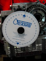
Yes ian, as Andrew said, get the timing as spot-on as you can. Use a cam-timing disc (Newman Cams do a good one at a very sensible price). To get the timing spot-on you will, as Andrew mentioned, have to elongate the holes in the cam sprocket. When you have got the timing as you want it, remove the camshaft and sprocket AS ONE UNIT. Look at the back of the camshaft flange and you will see a 5th (unused) hole. Run a drill though the hole and through the sprocket--doing it this way will ensure that the hole in the sprocket is exactly aligned with the hole in the flange (on the cam).Remove the sprocket from the cam, tap a thread into the camshaft flange and open up the hole (that you have just drilled through the sprocket) to allow the appropriate sized bolt to go through it. This way you aren't relying on the tightness of the sprocket-to-cam bolts to hold everything in location, which might be difficult now that the 4 sprocket-to-cam bolt holes are no longer round.
thumb.gif
smile.gif
 
Gents, Thanks for the replies. Tom, I appreciate using a modified timing sprocket to align the two dots and then using a grub screw to secure the setting, but what is the procedure when using a timing disc - surely this must be the most accurate way of setting the exact timing?? Also, do you know of anyone who could supply a vernier camshaft sprocket rather than modifying a fixed one?? Any engine builders out there care to comment??? Thanks.

Ian.
 
Evening Ian;
look online at:- 'timing a camshaft with a degree disc' and you will find u-tube films and written articles on the subject. Unfortunately, they all seem to be on American engines whose cam-shaft manufacturers give much more data regarding the camshaft than we can obtain, but the basic system is the same. I have looked at a number of Italian sites (Lavazza, Gattegna and Gozzoli) and nobody seems to sell Vernier cam sprockets for the 500/126.
banghead.gif
cry.gif
 
Thanks for the info gents much appreciated, I have an appointment with my local engine tuning and all round engineer chap later this week. I think I'll have a word about the possibility of developing a 'vernier' type camshaft sprocket and will post the results. Cheers.

Ian.
 
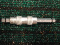
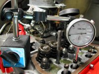
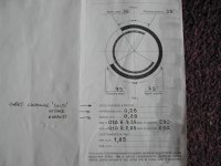
Well, having finished the cooler my attention has been focussed on slight rough running, so knowing that I have a 'slightly' miss-timed camshaft I thought that I should at least find out just how far it is from perfect. Engine out (again). I have obtained all the required gear for the investigation in line with the very good 'Blitz Racing' article - DTI and stand, Degree Disc, TDC indicator and a piece of wire for a pointer on the Disc. All the tools came from Ebay at remarkable low prices I might add!!! Getting the DTI set up was a faff, but a good exercise in patience nontheless! The TDC indicator simply screws into the No1 plug hole and is very effective, just rock the piston until you find the null point on the scale. Then set the Degree Disc to zero against the pointer. I have studied the information that arrived with my camshaft and noted that the work angle (Ang Di Lavoro) is 290deg for both intake and exhaust, so the point of max cam lift will be 110Deg ATDC. Those with sharp eyes will note that the quoted Valve settings are 0.28mm (cold) each !!!!! This seems rather different to what I know at the moment ?? Comments please?? I think that the quoted max lift is 10.725mm (my Italian is not good) Anyway before I could go any further I ran out of time, so the measurements come next and I find out how far my timing is out!! Watch this space!!

Ian.
 

Attachments

  • DSCN2485.JPG
    DSCN2485.JPG
    736.7 KB · Views: 35
  • DSCN2486.JPG
    DSCN2486.JPG
    711.5 KB · Views: 41
Greetings, have had the good fortune to get the measurements done today. I took the extra time to use my flywheel lock to prevent excess movement after setting the crank to 110deg ATDC. finding the null point on the cam took time, with the measurements taken from the top of the number 1 intake push rod. The difference between the point at which the cam stops lifting and the point at which it starts to drop is very small, but as a precaution made some reference marks on the cam and engine casing with a fine punch. (see pic) The cam was then set between the marks. After a lot of trial and error I eventually managed to set the chain and camshaft sprocket so that the marks I have made still lined up. Resetting the crank and cam marks together showed that they still did not line up, but I'm happy that the timing is now as close as I can get it without a vernier sprocket. the misalignment added up to approx one full cam sprocket tooth out one way and approx 1/2 a tooth the other way, but I have now got things as close as possible. I may still be a degree or two out. The development of a working vernier sprocket for this engine continues and we are trying to use a similar approach as the Shrigley Imp Vernier sprocket, but with differing camshaft mounting (see attached file) the danger is the lack of available space on the front face with the proximity of the oil pump to Camshaft. I will update when I have more information.

Ian.
 

Attachments

  • DSCN2494.jpg
    DSCN2494.jpg
    622.2 KB · Views: 34
  •    Shrigley Vernier Cam (imp).doc
    85.5 KB · Views: 46
I would read the max. valve lift as 7.25mm
10.75mm sounds excessive for an OHV engine.

Remember also, the lift at the cam lobe/end of pushrod may be different than the lift at the valve stem due to the rocker arm pivot not being equidistant from each end i.e. there may be a rocker ratio built-in.

The valve clearance quoted by the cam manufacturer is for valve timing checking/cam setting purposes. Sometimes you revert to standard Fiat valve clearances for running purposes, sometimes you use this initial setting as your new valve clearance. You need to check this out further.

Iirc standard Fiat camshaft timing checks called for valve clearances to be set to something like 1.00mm?, after the check, valves were reset to standard clearances for running.

As an alternative to making up a vernier type sprocket, if you measure the exact discrepency to be adjusted out, it may be possible to simply make an offset woodruff key for the crank sprocket (assuming such a key is used there). Iirc these offset woodruff keys were available from engine tuning supply companies or you could make your own, all you needed was a wider than standard woodruff key and a deft touch with a file if no machining facilities were available!

(Note:- Woodruff key is the half-moon shaped key fitted into the end of the crankshaft (also sometimes camshaft etc) which engages with and accurately locates the crank sprocket)

A Bing search shows these offset (Woodruff/crank/timing)keys are used on various car,motorcycle,small engines for tuning purposes.

Hth,
Al.
 
Hello Al. yes the max valve lift at 10.25mm does sound a great deal, reading the Cam data sheet again it does seem that they are indicating that the lift is indeed 7.25mm. I will investigate the offset woodruff key - it will be a simpler solution anyway!!! Thanks.

Ian.
 
Hi Ian,

You're welcome, anything to make life easier :)

I tried to do a Bing translation of the paragraph below the valve timing diagram.
It seems to say 'replace even slightly worn shoes (possibly cam followers?).
and check that valves can open a further 2mm at full lift before the valve springs become coilbound (as near as I can decipher the auto-translate)

Hopefully other members with good Italian can translate this correctly for you.

Always regretted studying French at school and not Italian. I think Italian is probably the loveliest sounding language and it certainly would have helped enormously with my lifelong interest in Italian cars.

Al.
 
Last edited:
Back
Top