Technical Ignition Coil Wires: the perils of being distracted

Currently reading:
Technical Ignition Coil Wires: the perils of being distracted

RDS

Member
Joined
Apr 12, 2017
Messages
310
Points
131
Hello all

Part way through fitting the Ultraspark electronic ignition module yesterday I became distracted and had a human memory failure!

The Ultraspark module is apparently vert sensitive to extraneous voltages so i wan to get this right first time. The problem is that my loom (car is 1987 1500) does not match the Haynes manual 100%.

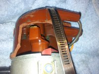
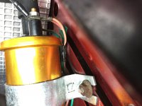
I have stripped out the large radio interference capacitor which was attached to the Negative terminal of the coil and also the previous owner's installation of a kill switch.

However I am left with the following wires:
Pink goes to positive on coil
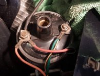
Brown wire factory crimped with a green wire (call this Green1) into one terminal goes to the Negative terminal (nb this is not the green wire from the capacitor or from the distributor)
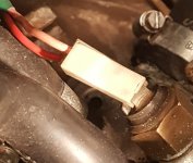
A further green wire (call this Green2) previously attached to the coil (but I cannot remember where!) now detached. Again, this is not the green wire from the capacitor or from the distributor, but instead trails back between the engine and bulkhead and disappears into a loom.

Questions:
What is Green1 feeding? The tacho?
What is Green2 feeding?
Does anyone else have Green2? Please can you have a look!
To which coil terminal is Green2 to be reconnected? I assume + terminal.

No doubt this can be done by trial and error but the cost of modules precludes it!

All help gratefully received.

Happy New Year

RDS
 
As I recall, on my 88 SE there was a pink ignition supply and a suppression capacitor attached to the +ve coil terminal (it should not go to the -ve!). To the -ve terminal there was a brown/white tacho sense wire and the green wire to the dizzy side terminal.

I don't think there should be any other factory-fitted wires connected to the coil. I would take the safe option and trace the mystery wires to see where they go. A previous owner may well have been messing with the wiring.

The safe procedure for your Ultraspark is to connect only the pink wire to the coil +ve terminal, then connect only the Ultraspark power and coil trigger wires to +ve and -ve coil terminals respectively. That should get you running.

Hope that helps.
 
Last edited:
Hello rachaeljf

many thanks for the reply. I went out to the car today and verified that i had connected the pink wire to the coil +ve terminal, the red ultraspark to the +ve coil terminal and the black ultraspark wire to the -ve coil terminal.

Of the other wires, i confirm the radio condenser WAS connected previously to the -ve coil terminal, however i did not reconnect.

There is also a mystery non-distributor green wire that was attached to the +coil terminal (it must be for powering something). It appears to be part of the loom and not aftermarket addition. Any ideas? The Haynes is of little help here.

In addition to the ring terminal on the end of the brown/white tacho sense wire that goes to -ve coil terminal, there is what appears to be a factory-crimped further green (non distributor) wire. As said, these were also left off while undertaking a trial start today.

Anyway, after priming the carb, the car would not start: the timing seems way out after fitting the unltrapsark. We had good spark at the king lead, though a poor spark on a new plug fitted to the king lead.

The battery discharged before we could check if we were getting spark on no.1 cylinder at compression stroke, and of course you can't do the static timing with the electronic module..... although manipulation of the distributor gets a spark (with ignition on) and we set distributor to just before spark happens.

At the same time the timing fingers were seen on the pulley to be about 20-25deg advanced for A (but not necessarily, THE CORRECT) Top Dead Centre.

I hoped to cross check this timing mark with the timing marks on the cam sprocket and the bell housing but the light was fading fast and i could see nothing that identified itself clearly in both cases as a TDC mark for the sprocket or bell-housing, as we bumped the engine over.

Could anyone please describe or better post pictures of what those two timing marks are supposed to be like?

(Of course, all those marks assume the engine was assembled correctly and the marks coincide with what they are supposed to indicate).

Happy New Year

RDS
 
Hi RDS, pics of timing marks can Ben found on the xweb wiki pages: https://xwebforums.com/wiki/index.php/StaticTiming

Not sure if this helps on my ‘88 I have two pink wires to the coil pos along with a black wire for the suppression condenser. On the neg terminal there is a brown and green wire.
 
Hello Neg

many thanks indeed for this - it is a great help! Though seeing those flywheel and cam sprocket marks as i push wont be easy.....

re the coil negative terminal, sorry to be pedantic but do you have either:
1 One brown/green wire or
2 one brown wire AND one green wire?
Do you have electronic ignition fitted?

Re Positive terminal, odd that you have two pink wires and i seem to have one pink and one green. One pink is from ignition switch, what is the other pink wire for?

thanks again

RDS
 
Yeah, it’s one green and one brown wire going good to the neg coil terminal and two pink/faded red wires to the pos terminal. Standard points setup.
 

Attachments

  • C03DA352-0A4B-40CC-9108-0675158D14EC.jpeg
    C03DA352-0A4B-40CC-9108-0675158D14EC.jpeg
    1.3 MB · Views: 141
Thanks Neg

all least we have established that the one green wire and the one brown are standard.

Where does your green wire go?

Mine does not go to the distributor - as per my earlier post i had already removed the green wire from the negative coil terminal to the distributor and am still left with one green wire and one brown/white wire to the negative terminal

why two pink wires?

Looks like it have to time mine from first principles to get this engine running again. I am sure they could have put index marks on the Ultraspark kit to get somewhere near before timing the thing up with strobe.

cheers

RDS
 
I asked an owner of a late model car. He has two pink wires too. The second pink feeds a thermoswitch on the thermostat housing, which then feeds the autochoke on the carb via a red wire. Thus the autochoke gets electric heating until the coolant gets up to temperature, along with regular coolant heating.
 
Wow! Really? I’ll have to check mine out, always wonderd what the red wire to the choke housing was for....
 
i cant see any reference in the extended Haynes manual. Mine's a 1987 car and it doesn't ring a bell: i can;t see where my extra green (not pink!) wire goes.

Can either of you post pictures of where the wire enters the auto-choke mechanism, please?

cheers

RDS
 
These photos are a Gran Finale model. The owner "Bert" prides himself on keeping his car pristine and absolutely as it came out of the factory. I don't have a photo of the carb autochoke, but the red wire should go to the choke operating mechanism on the side of the carb, which looks like a can with two small coolant pipes attached to the end.


This doesn't help with the mystery green wire I'm afraid. I think you will just have to trace it to see where it goes!
 

Attachments

  • Gran Finale coil.jpg
    Gran Finale coil.jpg
    78.2 KB · Views: 185
  • Gran Finale choke thermoswitch.jpg
    Gran Finale choke thermoswitch.jpg
    74.3 KB · Views: 132
Thanks Rachaeljf

most useful, i do not think that is the same as mine but i will have another look.

The mystery over the last few days is also why i can't get the car to fire up after fitting the electronic ignition, leaving off the 1st mystery green wire and also the brown/white tacho wire and the 2nd mystery green wire.

Strong spark from the king lead, but weak spark from the spark plug against the engine block!

cheers
RDS
 
Is this kit number ICP-EK048?

The kit you fitted should be set up so that the spark is generated when the rotor arm is pointing to a contact in the cap. I have read of someone using this kit and being very happy with it, but I have also read that another chap found the spark was being generated when the rotor arm was in between two contacts, meaning the unit was not correctly "indexed." This is very hard to check if there are no indexing marks on the unit.


I made my own kit with a Powerspark module. I had to make up a rig to see whether I had it indexed correctly!
 

Attachments

  • 2018-01-28_00.02.01[1].jpg
    2018-01-28_00.02.01[1].jpg
    1.4 MB · Views: 68
  • 2017-09-14 21.33.46.jpg
    2017-09-14 21.33.46.jpg
    1.8 MB · Views: 105
Hello

yes that's the exact model
https://www.ignitioncarparts.co.uk/PartDetails.aspx?s_pc=ICP-EK048&s_vid=

it is interesting what you mention re the indexing issue and lack of definite initial mark, because those issues were exactly what went though our minds when we were having to manipulate the distributor a ling way to get any evidence of spark.

Can you point me to the post that you read re the other chap's experience please?

Re your version, that's very good. Powerspark told me that they didn't have a correct base plate, module or ring. Did you have to modify, if so how?

re your rig, if i interpret correctly, you have cut away an old cap and placed a strap in lie with the terminal for no 1 cylinder to see if the rotor lines up?


cheers

RDS
 
Last edited:
If you google the kit number you should see the posts in the UK Owners Club forum. I don't go there any more.

I made up my own base plate after a bit of experimenting. The test rig was made up using a broken dizzy cap I had lying around.

The Powerspark kit was I think for a Lucas dizzy, but I can't recall now!
 
thanks for that - oh dear, i wish i'd seen that post before purchase. I have a sneaking suspicion that's what is happening here. I need to get an old sacrificial distributor cap to test....

anyone know what other Fiats share that cap so as to widen the search?
 
Can anyone help me trace wire colours for my 1982 FIAT X 1/9. A few years ago a small pin hole fuel leak led to an engine fire that melted my ignition wire insulation colours before being put out. (Quite a site, engine fire-fighting with a green light).
I have a coil with a Magneti Marelli white ballast resistor with two copper wires. Remnants of pink and green wires and a grey/white wire. Distributor is a Magneti Marelli S135. Hoping to change over to Lumenition electronic ignition perhaps eliminating spark ignition source of fire.
Any available pics of ignition/engine bay greatly appreciated.
 
Hello rachaeljf

I meant to say ages ago that I solved my issue and wanted to make up an ignition system like yours, however what did you do for the reluctor that slips over the central cam? Different distributors seem to have different shapes (even 4 cyl distributors).

thanks in advance.

PS Milan, i fitted my own ballast resistor to bring the new hi-perf coil down to the correct resistance (I will revert to the Marrelli in due course though and eliminate the ballast) but i do not have a grey/white wire as you state. Mine does not have the carb heater or idle valve set up on the carb, yours may be part of that, Haynes is merely a guide, I find, to the wiring)

cheers
RDS
 
Last edited:
Back
Top