

You are using an out of date browser. It may not display this or other websites correctly.
You should upgrade or use an alternative browser.
You should upgrade or use an alternative browser.
Technical Uno Turbo ECU Pinout Diagram
Currently reading:
Technical Uno Turbo ECU Pinout Diagram


Ignition, fuel injection or both ECUs?
 If I could both, that would be a great help :worship:
This is the ignition ECU as used on all petrol Mk2 non-FIRE engines.

Do you have a Haynes manual? If so the wiring diagram for the Injection ECU is number 24 in section 14. If not, I can go and dig them out.

Do you have a Haynes manual? If so the wiring diagram for the Injection ECU is number 24 in section 14. If not, I can go and dig them out.
No I don't have a Haynes manual, if you could I'd be very greatful, thank you for all your help
I've PM'd you with the info.
You've been a great help, thank you for the link. I've saved the .PDF to disk now, i'll look forward to flicking through it later.
I'm actually trying to find the following
RPM Signal - Injector Signal from ECU
Throttle Signal - Bosch Throttle position sensor in engine bay (Need a pinout for this)
Speed Signal - Would the crank shaft sensor work?
This is all needed for an Apexi boost controller that i'm trying to pick up next week.
Most of it seems stright forward, its just the Speed Signal that im not sure about...
Thinkin about it, the Throttle position sensor is only going to be a variable resistor isn't it? So I would imagine that pin 2 from this unit would give me the output that I need to put into my boost controller...
Anyone with any advice on this would be super handy
Anyone with any advice on this would be super handy
Throttle signal can be got from the TPS as you say. RPM can be got from the tacho gauge feed or from one of the injector wires, depends on the flexibility of this new gizmo of yours as to how it can count 1 RPM.
Speed is not captured electronically. You can get speed from a gearbox sensor from a later FIAT, but it will sit where your speedo cable is now, so no speedo readout then.
Speed is not captured electronically. You can get speed from a gearbox sensor from a later FIAT, but it will sit where your speedo cable is now, so no speedo readout then.
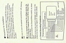
I've finally got my Apexi Boost Controller through Its not quite as simple as it looks I understand that I have to splice it into the existing ECU wiring, I would just like to double check that I'm doing it all right before I start....
Here is a picture from the manual. Would you kindly just go over the pin outs of the ECU again, I think we agree that pin 2 on the TPS will give me the position feed (As it is just a variable resistor) really greatfull for this, thank you for your time :worship:
Its not quite as simple as it looks I understand that I have to splice it into the existing ECU wiring, I would just like to double check that I'm doing it all right before I start....Here is a picture from the manual. Would you kindly just go over the pin outs of the ECU again, I think we agree that pin 2 on the TPS will give me the position feed (As it is just a variable resistor) really greatfull for this, thank you for your time :worship:
Attachments
The speed signal will be collected via a GPS device that converts movment into a square waves all high tech stuff for something thats never designed for an uno turbo, sayin that... If a Scuby or Evo can have one, then why cant we?
all high tech stuff for something thats never designed for an uno turbo, sayin that... If a Scuby or Evo can have one, then why cant we? The only wire you haven't accounted for from that diagram is RPM then? It says an injector signal is OK, so you can use one of them I would guess. There isn't enough information for me to comment any further. I have no idea how this thing works or what it is supposed to do. I have no idea what kind of signal it wants and what frequencies or anything. Speed signals come in different shapes and sizes too. I would like to know what it would do with a speed signal anyhow. It's all very vague without more info.
An Apexi AVC-R is a boost controller that has an electronic solenoid that fits where a normal waste gate would go. If you want to run it globaly, you can set the pressure to 0.7 bar, wire in a scramble switch and tell the unit to increase boost to 1 bar for 20 seconds as and when you want it (flick the scramble switch) . If you want to have different boost levels for different gears (like me) then it is possible to set up the system to have 1 bar of boost in 1 and 2, then .8 bar of boost in 3rd, finally .7 bar of boost in 4th and 5th... How ever to do this I need the ECU pin outs (as displayed in the diagram above)Sadly the manual is not in english, but i will find something and put a link on here as soon as i can
How will you tell the boost controller what gear you are in; there are no sensors for that? You need to find out from fourms or whatever which signal types/ frequencies have found to be acceptable to this unit before you know whether you can fit it or not in my opinion. Alternative is to guess and wire it up and see what happens.
The unit works out what gear you are in using the speed (which is not available) and the RPM (From the 1st injector) I am currently talking with Apexi to find out if I can use a GPS Speedometer Speed Sensor
http://thetachman.com
to see if this square wave that increases/ decreases with the speed output will do the job.
Now going back to the RPM signal, i really don't think that splicing it straight off off of the injector is a good idea, it would have to be taken from the same place as the RPM counter on the dash... as the signal has been insulated.
At 30MPH I could be in any gear, so I don't quite get that part. Perhaps you are able to set it up with full throttle, full RPM shifts in mind all the time.
Thee dash uses the negative terminal of the coil of course. You will get a different frequency and type of "pulse" from the coil versus the injector. In either case it doesn't matter where you splice the wire in reality. The coil will pulse twice per revolution and the injector will pulse once every two revolutions.
I hope the manufacturers can make it all clear as I don;t think I can help on this one.
Lewey after having a chat with Apexi with regards to wiring in the RPM signal, they have come back to me and written this...
"For the RPM signal it varies by application, however, for the most part you can take the signal off of the Crank Sensor signal, should be a 0-5V reference signal"
Do you know how does this fit in with the Uno Turbo ECU, and is it easily accessible to splice?
I'm really grateful for the time your putting into this mate, if we can crack this together its got to be worth a few thank you:worship:s
lol, and if you were local, a few pints too
were so close to finishing this little project, I've fitted the boost controller, I've ordered a transducer to get a VSS speed signal, I know how to get the throttle position... I just need to work out how to get the crank shaft sensor? Can anyone help with this?