General Radio turns off after 20 mins!!

Currently reading:
General Radio turns off after 20 mins!!

Do you need help unlocking your radio?
Get your code instantly using our radio unlock service 🔓🎶
Have just bought 2009 Ducato Timberland m/h. Have located permanent and ignition +ve feeds and was about to modify along the lines suggested by stewartkingswood. However, am now reluctant to do so as he warns against doing this on 'latest version'. Does anyone know what the problem is ?
 
This works on x250 or later models
 

Attachments

  • Radio reset.jpg
    Radio reset.jpg
    257.5 KB · Views: 1,206
Hi,
Sorry for not replying earlier been away, however this is the method I have used in the past on my Peugeot Boxer Motorhome to alter the radio settings.

THIS METHOD SHOULD NOT BE USED ON THE LATEST VERSION OF THE BOXER OR DUCATO

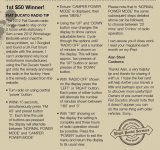
To simply eliminate the 20 minute cutoff but retain the ignition on switching feed is quite simple. You need a couple of feet of twin core wire (speaker wire is ideal as the current carried is very low) a diode and a switch. mount the switch in a convenient place and connect one of each of the two cores to either side of the switch. Remove the radio and with a multi meter or test lamp establish which wires are the permanent live and ignition switched feeds.

On Fiats the permanent live should be the thick red wire, the ignition switched feed is a thin yellow/blue wire. Once you have established the ignition switched feed cut it through about 50 mm from the socket and insert the diode into it (check it's the right way round by switching the ignition on, if the radio comes on then it's the right way round, if not reverse the diode).

Connect one of the two cores from your new switch to the permanent live and the other to the radio side of the diode. Now your radio will still switch on and off with the ignition but by operating the switch you can have it on for as long as you like without the ignition on.

To power your radio from the leisure battery run a new wire from your leisure battery (with a 10 Amp fuse as near to the battery as is possible) and cut the red from the original feed (again about 50mm from the socket). Connect the new wire to the red tail to the radio socket.

DO NOT USE INSULATION DISPLACEMENT CONNECTORS (SCOTCHLOCKS) FOR ANY OF THE CONNECTIONS. EITHER SOLDER AND INSULATE OR USE PROPER CRIMP TERMINALS AND CONNECTORS.

Parts needed (all from Maplins)
Diode Maplins Part number N72CA
Bell cable length to suite wher you are fitting the extra switch
Switch Maplins Part number NOOAR
10amp power wire and in line fuse for the leisure battery wiring (from local Car Accesories shop)

Thanks to Dave Newell for publishing the article in Practical Motorhome Magazine

I hope you will visit me in prison if I have broken any copyright laws!!!
Regards
Stewart


OK, sorry to ask what is probably a daft question, but I am thinking about using that technique on our 2003 motorhome as the radio has reached the end of my patience due its behaviour.....

BUT Maplins have now become online only, I think, and do not seem to list any components any longer....

Hence the reference number for the diode N72CA gives a "no products match that" type response, so,

May off chance question, based on my not being an electronics specialist, is what are the characteristics of this diode and can ANYONE give me a link to something that will do the job ?

I know being DC the calculations are easier, supposedly, but that is about the limit of my knowledge...... what current does the radio consume, are there any other things that need to be considered ?

So, can anyone help me ? I know the thread is old and that things have moved on, but of course my motorhome is one of the old style ones....
 
The 1N4000 series of diodes are all probably electrically adequate, but not perhaps sufficiently physically robust in a vehicle enviroment. The 1N5400 series are more robust with thicker lead out wires, and are rated at 3A.

With my x244 PVC (IH Tio R), I approached the radio problem from a different route.

I actually wanted to include a 30 minute sleep timer into the system, as well as removing the radio load from the starter battery. I ran a new cable from the habitation 12V distribution board. For stage 1, this cable was connected to both the B+ and Ign+ leads from the radio, with the original cables left available.

For stage 2, I fitted a micro changeover relay under the dashboard. This relay is operated from the original Ign+ supply for the radio. With the ignition on, the radio Acc+ is connected to the supply from the hab battery, and with ignition off the radio is connected to a miniature changeover switch at the rear of the vehicle (sleeping area). The changeover switch allows selection of either timed availability of the radio, or continuous availability. Irrespective of the switch position, the radio functions normally with the ignition on, but is rarely used while driving.
 
Do you need help unlocking your radio?
Get your code instantly using our radio unlock service 🔓🎶
Back
Top