Introduction
Hello Fiat forum,
I have a 126 with a 1.1 FIRE in which is fine for what I need, motorway is no bother and it's a bit of fun around the countryside, but last year a Van Aaken kit came up on eBay and I was clearly on a mad one because I ended up buying it. I thought I'd see the summer out enjoying it NA and get the kit installed over the colder months, which is now!
I intend to drive it often, commute etc so I'm trying to make it as reliable as possible, oil cooler, reduced compression ratio, intercooler as well as maybe some less well founded (?!) stuff like polishing the combustion chambers to reduce knocking. I guess while it's all in bits, I may as well. I'd like to have the confidence in the build to turn the boost up if wanted.
We know this engine wasn't meant to be turbo'd and I don't have unlimited budget so I'm trying all I can to get full enjoyment from it for as long as possible. I'm no expert but YouTube has made me believe in myself to maybe extreme levels . I have a modest workshop so I can do a bit of this myself.
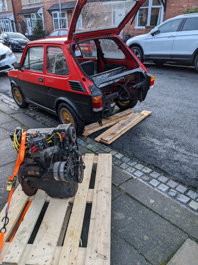
Today was engine out day, only a bit of rain so no complaints.

The plan in a rough order is:
I'll keep updating this thread as I go.
I have a 126 with a 1.1 FIRE in which is fine for what I need, motorway is no bother and it's a bit of fun around the countryside, but last year a Van Aaken kit came up on eBay and I was clearly on a mad one because I ended up buying it. I thought I'd see the summer out enjoying it NA and get the kit installed over the colder months, which is now!
I intend to drive it often, commute etc so I'm trying to make it as reliable as possible, oil cooler, reduced compression ratio, intercooler as well as maybe some less well founded (?!) stuff like polishing the combustion chambers to reduce knocking. I guess while it's all in bits, I may as well. I'd like to have the confidence in the build to turn the boost up if wanted.
We know this engine wasn't meant to be turbo'd and I don't have unlimited budget so I'm trying all I can to get full enjoyment from it for as long as possible. I'm no expert but YouTube has made me believe in myself to maybe extreme levels
. I have a modest workshop so I can do a bit of this myself.Today was engine out day, only a bit of rain so no complaints.
The plan in a rough order is:
- Polish and cc combustion chambers
- Strip down bottom end and inspect bores/crank/pistons - hopefully all will be in good shape, I expect to have to get new rings but these aren't ordered yet, don't know which size I may need depending on bore wear. Interested to hear what you'd gap these at.
- Fit any new bearings and seals identified as bad along the way, inspection points will be end float, big end bearings and seals
- Turbo oil feed from upper tap of oil pump/filter housing. This takeoff was included in the kit but it doesn't seem restrictive as much as I have seen on other turbo feeds, any advice on what kind of restrictor I need would be much appreciated
- Turbo oil drain fitted to new sump, above oil level
- Reduce compression ratio to about 8.5:1. My preferred option would be to skim the pistons but I'd need to do some measurements on them first to see what I'd be left with! Second option is work the heads pre-polish and last option is a compression plate. I don't fancy the plate because it's the most expensive option and I don't want to mess with the valve timing.
- Install the thermostatic Mopar oil takeoff (filter sandwich type) and radiator
- Find somewhere to mount an intercooler - thinking of making a shroud that will duct air over it picked up from under the car, or from one of the side vents, with the oil cooler behind it
- Make an exhaust up - bearing in mind that I want it to be a useable car and it's very noisy right now, I'd like to quieten it down a lot. The previous owner was frugal yet smart and used a mid box from the donor car (Sei). Any suggestions on a decent backbox which isn't huge would be greatly appreciated
- Clean and paint a few bits on the engine, I don't want a show car engine but it would be nice to have something that looks better than when it was pulled out. Why not ey?!
- Blow up the stock gearbox
I'll keep updating this thread as I go.