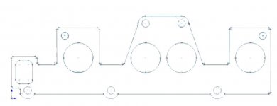
Im currently trying to convert this picture of an inlet gasket into a CAD model...so I can build up a model of my full intake system.
I scanned it in in two parts and stitched it together as one file at 1:1 scale.
I want to pick out the edges and lines from the image - basically finding the edges and the holes if this makes sense - as Im gonna convert the colour depth to 1-bit so I can pull the dimensions off from a line art picture in the CAD package.
Ive erased the logos printed on the gasket face, although not very well...does anyone know how I can pick the edges out? I want a picture like the first attachment, startuing from the second. (although the attachment is 16.7m colours).
Ta
Attachments
Last edited:


