Technical Multiscan adapter

Currently reading:
Technical Multiscan adapter

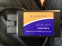
ELM327 is kind of a passive device; the 12v input voltage is internally regulated to 5v to feed the µchips and other components so IN THEORY it shouldn't send more than 5v to the CAN pins which (both A-B and L-H channels) are the only ones connected (beside power) on GPs.
MES requires only the yellow adapter or direct connection, maybe by trying other color adapters you unluckyly sent 12 volts where it shouldn't :-(

BRs, Bernie.

You’ve kind of reassured me Bernie ?, I did measure 4.xx volts on one of the pins can’t remember which one though,

I’ve also noticed after taking a closer look at the obd port, it looks like the female pins are spaced to far apart, now this is making me wonder if that’s the problem,

I’ve ordered another diagnostic lead from a guy On eBay who said he Modifies them hisself and knows it will definitely work, Just to rule out leads

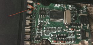
What I’m going to do with the cheap WiFi reader is take it apart and connect it back up to the obd port then Check for continuity, I’ll probe the Wifi internals and Then back probing the obd port to make sure each pin in the socket is getting a connection,
 
Last edited:
Hi Chris,

in reply to the PM you sent me (so other can read too) :

Pin 7 on the OBD port is for the K-Line.
The K-Line is a different communication protocol, similar to the RS232 (serial), which is not used on GPs but may still be used on other (or older or made under license) models. It is wired in the yellow adapter for compatibilty with those cars.
BTW, it uses only a single wire and the ground and is able to adress each receiver individually.

So to make it short, don't get mad about it !

BRs, Bernie

ps: want some reading ? Have a click on this:

https://www.irjet.net/archives/V4/i7/IRJET-V4I7181.pdf

If someone here helped You fix -or better, understand- your issue, hit the thanks icon @ bottom right corner, it's free and makes us feel helpy ;-)
 
Last edited:
Slight update, connected yellow adaptor and ELM327 to vehicle, tested the wiring from EML327 (internal pins), to vehicles OBD socket (back probed) with multimeter. Connection was all good,

So it’s now looking like the Usb lead isn’t compatible with the vehicle even though it says in MES it should work, , got a new one on order From another seller on eBay and been told by the guy that he removes the resister his self and can Guarantee The lead is fully Compatible with the vehicle, (His business is vehicle diagnostics)

I’ll update when it arrives, ?
 
Last edited:
Does MES (or at least your laptop) see the ELM327 interface ? You also need to assign it (in windows) the same Com port that MES will be setup to communicate to. Even if it's USB, it uses a virtual Com port !

BRs, Bernie

If someone here helped You fix -or better, understand- your issue, hit the thanks icon @ bottom right corner, it's free and makes us feel helpy ;-)


Hi Bernie,

I’m sure MES does see the interface connected, because when I go into MES settings then interfaces it comes up on COM6, I pressed test and it says ok for all of them and says this interface EML327 1.4b is Compatible and should read all CAN modules, (something like that)

I’ve also pressed the Scan for interfaces option and that also comes back all good,

I’ve also gone into device manager on windows and checked all the settings and they match with MES,

If the new lead doesn’t work, the seller who is selling the lead has said he will remotely set everything up,

Maybe it’s a fault with me when I de-soldered the resister and damaged the board, But I couldnt see anything wrong,
 
Last edited:
Maybe it’s a fault with me when I de-soldered the resister and damaged the board, But I couldnt see anything wrong,

Still don't know which resistor you removed ... it was written 121 but that doesn't mean it was the right one ...

BRs, Bernie
 
Still don't know which resistor you removed ... it was written 121 but that doesn't mean it was the right one ...

BRs, Bernie

I’ve chucked that lead in the bin,

Update though,

New lead arrived today and BINGO we have success, all modules are found on the scan, I need to get the registered version of MES though to read the Airbag module now, Thanks all for the help
 
Hi Laurent, would be nice to share the link you used for the interface and also some pictures might help other to find out ...

Cheers, Bernie.
 
Hi Bernie,

This is the seller https://ebay.co.uk/usr/djwwautodiagnostics

He doesn’t have them listed for sale, I contacted him and asked if he does one for the grande, very helpful guy,

This is the lead he supplied me, it’s already modified and works great, it was about £15

The other seller has agreed to send me another lead, I’ll test that and update also with that one, but I would highly recommend the seller I’ve linked,

Just need to get the registered version of MES now to read the airbag light,

Massive thank you to all though regarding this, If it’s aloud I’ll make a guide on how to set up a ELM327 with MES if it helps anybody who’s new to this like I was,

Regards
Chris
 

Attachments

  • image.jpg
    image.jpg
    2.5 MB · Views: 29
Last edited:
This post contains affiliate links which may earn a commission at no additional cost to you.
Thanks for that last update Laurent !

This is exactly the same interface that I have (got the 3 versions: USB, Wi-fi & BT) which I have modified myself (by removing 120 Ω resistor between pins 6 & 7 of CAN transceiver chip). Attached is a drawing of how it may also be terminated, and one that shows how a CAN bus should be terminated ...

BRs, Bernie

If someone here helped You fix -or better, understand- your issue, hit the thanks icon @ bottom right corner, it's free and makes us feel helpy ;-)
 

Attachments

  • CAN Termination.JPG
    CAN Termination.JPG
    40.5 KB · Views: 35
  • CAN transceiver SN65.JPG
    CAN transceiver SN65.JPG
    58.9 KB · Views: 34
Thanks for that last update Laurent !

This is exactly the same interface that I have (got the 3 versions: USB, Wi-fi & BT) which I have modified myself (by removing 120 Ω resistor between pins 6 & 7 of CAN transceiver chip). Attached is a drawing of how it may also be terminated, and one that shows how a CAN bus should be terminated ...

BRs, Bernie

If someone here helped You fix -or better, understand- your issue, hit the thanks icon @ bottom right corner, it's free and makes us feel helpy ;-)


I’ve bought a Bluetooth one, it’s being shipped from AliExpress, I’ll post a picture up once I’ve taken it apart, And if don’t mind Bernie Could you tell me which resister to remove so I know it definitely the correct one ?
 
Last edited:
Hi Bernie, would you kindly point out what resister needs removing on the WiFi ELM327, there’s a red arrow going to the resister I think it is, is that correct?
 

Attachments

  • F2B5EDCA-2F26-4226-BC40-343BD5BF77BE.jpeg
    F2B5EDCA-2F26-4226-BC40-343BD5BF77BE.jpeg
    857.5 KB · Views: 38
Looks like it's the right one. Do check though if the track goes to pin 6 or 7 on the CAN transceiver chip AND to the PBD connector ... At least it has the correct value: 121 = 12 + 1 zero = 120 Ω
Any picture of the other side ?

Cheers, Bernie.
 
Looks like it's the right one. Do check though if the track goes to pin 6 or 7 on the CAN transceiver chip AND to the PBD connector ... At least it has the correct value: 121 = 12 + 1 zero = 120 Ω
Any picture of the other side ?

Cheers, Bernie.

Not the best pic, phone struggles to focus with close up,
 

Attachments

  • 00DFF360-702F-44AD-A36F-A734655F7213.jpeg
    00DFF360-702F-44AD-A36F-A734655F7213.jpeg
    1.5 MB · Views: 35
Hi Laurent, can't see much indeed !

The resistor to be removed (if present !!) is connected between pin 6&7 of the OBD transceiver chip AND on pins 6&14 (CAN L/H bus) of the OBD connector, so one leg, (or the trace it was solderd to before removal) must be O Ω with OBD pin 6 or 14. If so and the other leg has 0 Ω with the opposite pin, that is (was) the right resistor ...

BRs, Bernie

If someone here helped You fix -or better, understand- your issue, hit the thanks icon @ bottom right corner, it's free and makes us feel helpy ;-)
 
Last edited:
Back
Top