Technical Maximum load alternator Ducato 2021

Currently reading:
Technical Maximum load alternator Ducato 2021

Labora

Member
Joined
Aug 14, 2021
Messages
20
Points
53
Hello, my first post...
I would like to charge a series of LiFePO4 cells from the starter battery while driving. For this I use DC to DC converters which have a 30 Ampere rating and are fed from the starter battery. The question I have is how much current can I draw from the alternator, the starter battery. According to my information, there is a Valeo 200 A alternator in the car. A revision company gave me the tip never to put more than 60% permanent load on an alternator. That comes down to 120 A. Can someone tell me what the power consumption is under normal circumstances? So for example lights on, no air conditioning and other large consumers and a normally charged starter battery. Suppose that is 60 A, then I could reserve 2 * 30 A for DC to DC. Also important is how much current the alternator is charging the battery with. I hope that my question is clear.
Thanks in advance and my regards!
 
I think you will struggle to get any definitive answer on this.
How much current the alternator is charging the battery with depends how flat it is.
Apparently to cover themselves from warranty claims Fiat say your secondary batteres should not exceed 20% of the capoacity of the main battery
Which is about 20ah
The handbook gives equally unhelpful advice like if you need to charge the battery take it to a FIAT dealer.
Of course of you are going to make use of it as a camper you have to have a bigger secondary battery than that
Even though the extra work will probably shorten the life of the alternator, just as any other usage of the van wears it out.
On my X2/50 I had 2x100ah secondary batteries (one leisure one starter) wired in series with th main battery through a voltage sensing relay. It worked well for 12 years 95,000 miles and is still ok. Now I have an X2/90 with 4 x 100ah secondary (starter) batteries wired in series with the main battery through a relay activated by the D+ signal, which has worked well for 6,000 miles 4 months so far.
I have never had a B2B charger because its always worked well without.
And I am using ordinary starter batteries (2 of these under each seat https://www.tayna.co.uk/car-batteries/varta/h3/ ) as my secondary batteries
I'm not advising anyone else to do this - just saying thats what I have done and its still serving me well.
But if you do it you do it at your own risk same as me.
 
Last edited:
An empirical but valuable approach. Thanks a lot!

Unfortunately I cannot build for the next few months but I am going to try it with two DC to DC chargers of 30 A each. There is some competition in that market now and I think I can buy for less than € 200.

Today I had a discussion about the tolerance on that 200 A of the alternator. As I will not be travelling in very hot areas I think it is a responsible risk.

I want to keep the principle the same as it is now. At the moment, the inverter solution is started with a 200 A relay. That relay is controlled by ACC+ with a timer relay (~ 1 minute waiting time). D+ I have not been able to find yet, that is preferred. D+ could be amplified with an optocoupler relay card if it is a wire from the board computer.
 
Sorry I should, of course, said the batteries are wired in parallel not in series, and I can't see how to edit my post now.
Bit like when I take a wrong turning its most likely to be in an area I know well - just not thinking.
Call it a Senior Moment - Send for Dr Shipman.

I think you will be alright with a 200A relay - Fiat say you can put up to 300ma through the D+ (if you can find it which is not easy on a Sevel van without the converters socket. There is a thread running on that subject. But if you are lucky it might have the converters socket - mine has even though it isn't on the spec sheet or been charged for) My 200A relay draws 170ma. Before that I had a 500a starter relay which drew about 700ma - but I just had that activated by the ignition switch, not the D+. If you overload the D+ you will probably find the alternator won't supply current at low revs, if at all.
To minimise resistance and maximise charging I use 25mm2 cable without fuses - again some people will baulk at that I know - but I have got the cables very well insulated and protected.
 
If you overload the D+ you will probably find the alternator won't supply current at low revs, if at all.
Better save than sorry in this case, thanks for the warning. I've read that people use it for relay input, I'll stick with an optocoupler approach.
To minimise resistance and maximise charging I use 25mm2 cable without fuses - again some people will baulk at that I know - but I have got the cables very well insulated and protected.
I have to go straight to the back of the van and plan on using an aluminium strip of 25 * 5 mm for that - in the isolation between steel floor and walking floor. Equals ~ 60 mm2 copper, but it is a L4 so it is a long way.
Finding D+ ... It seems to be a maroon/green wire but the one I probed was not D+.
 
Hi Labora

Here is a very rough estimate of a rainy day scenario for a van that's been running for a while, so the starter battery has by now been charged up after a cold start and the charging current has dropped to a residual level.

Headlights and Side/Tail Lights 8 Amps
Heater blower on medium speed 8 Amps
Wipers 8 Amps
Engine Management 4 Amps
Vehicle Battery Charging 5 Amps
Electric Steering (Not Cornering) 5 Amps
Radio 2 Amps

Total 40 Amps

So if your B2B converters are demanding another 60 Amps, that totals 100 Amps which the Alternator should be happy with long term.

If you want accurate figures, I suggest temporarily using a DC current meter of the "clamp on" type.

I like the idea of your Aluminium "Bus Bar". If it is 25 x 5 mm and 4.7 metres long that gives a resistance of only 0.001 ohms. Your 60 Amps will then drop only 60 mV and you will lose only about 0.4% of your B2B input power per bus bar (I don't know if you have a second one for ground). I think you could probably use something a little smaller without noticing, but there is nothing wrong with overkill !
 
Doesn't surprise me you are having trouble finding D+ because in my experience whoever makes FIAT wiring looms has an annoying habit of using whatever colour wire they have to hand.
I have never had a B2B charger - one of the things that put me off was the small capacity and inefficiency of the power lost in the charger instead of it all going straight through to where its needed. In my experience in practice you rarely get the figures the salesmen claim for these sorts of things - as in you are lucky if you get half the claimed maximum range for an electric wheelchair etc. Wheras with a short thick leads connecting my secondary batteries (they are under the front seats so very close to the main battery) to my main battery they charge PDQ, certainly more than 30a - especially with regenerative braking so I chose starter batteries to cope with the higher charging current.
If the batteries are at the other end of a long van I can see you probably need a B2B charger to boost the voltage - even with your thick conductors.
I'm just curious as to why have 2x30a B2B chargers instead of one 60a ?
 
Last edited:
Here is a very rough estimate
...
Total 40 Amps
Really helpful, thanks!

So if your B2B converters are demanding another 60 Amps, that totals 100 Amps which the Alternator should be happy with long term.
The only thing I am asking myself: Is the supply to the starter battery fused and if, what is the rate.

I like the idea of your Aluminium "Bus Bar". If it is 25 x 5 mm and 4.7 metres long that gives a resistance of only 0.001 ohms. Your 60 Amps will then drop only 60 mV and you will lose only about 0.4% of your B2B input power per bus bar (I don't know if you have a second one for ground). I think you could probably use something a little smaller without noticing, but there is nothing wrong with overkill !
Couldn't resist checking the numbers... Great work! Overkill? Probably indeed ;-) It is aluminium 6060 T6, so it is tempered. Covered in a proper shrink tube it will go from front to back over the floor and then to the left, more or less in a "L" shape. So there are some welds. The nice thing about applying a TIG torch without filler is that one achieves instant annealing. Bad for screw threads but great before bending. For ground I'll use chassis for the long distance and then go further with wires. If you're interested, see https://vanderworp.org/electrical-resistance-of-the-car-body/.
 
Doesn't surprise me you are having trouble finding D+ because in my experience whoever makes FIAT wiring looms has an annoying habit of using whatever colour wire they have to hand.
Equals COVID times Italy? LOL!
If the batteries are at the other end of a long van I can see you probably need a B2B charger to boost the voltage - even with your thick conductors.
I'm just curious as to why have 2x30a B2B chargers instead of one 60a ?
I understand your reasoning. Thing is, I am building a mobile office. For that I have 6 kW batteries in total. Not using LiFePO4 means adding a lot of mass in this situation. What kept me away from B2B was pricing mainly. 2 * 30 A keeps it redundant, it is mission critical. The 230 V chargers are also dual set up. It is all a bit more wiring and work but I am okay with that. And... it is a way to avoid import duties ;-)

Addendum 1: It is my impression that productivity is pretty good these day with all the MOSFET integration, but yes, I am aware that I'll loose energy compared to direct charging a second lead acid battery.

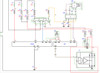
Addendum 2: Added schema for D+...
 

Attachments

  • 2022-01-29_15-05.png
    2022-01-29_15-05.png
    99 KB · Views: 79
Last edited:
A number of points you may need to consider,

A 200 amp alternator will not deliver 200 amps continuously or at low engine speed. At idle speed expect around 130 amps maximum. The van systems could take around 50 amps without considering charging the van starter battery. These are measured values.

A 30 amp battery to battery charger can take up to 40 amps from the van system.

A battery to battery charger from most manufactures does not need D+, it will detect engine running from voltage changes.

Any additional load greater than around 70 amps will reduce reliability. Consider why the manufacturer fitted a 200 A alternator for a van that only needed 50 amps.

Consider fitting lithium batteries, 50% of the Amp hours of lead acid will give the same effective usable power, charge faster and twice as efficiently. also there will be considerable weight saving and a much longer service life. Lead acid batteries in a van conversion rarely last longer than 2 to 3 years and still have usable power capacity

Your alloy bar will be difficult to terminate and insulate from the van metal, use welding cable with crimped copper tube terminations with correct fusing at each end. I think one contributor suggested no fuses, this is incredibly stupid and unsafe.

Mike
 
Thanks for the update. It is good to see confirmed that 2 * 30 A is quite reasonable. In addition, the engine compartment is built so full, with the exhaust close by, that the ventilation near the alternator is not optimal either.

The car is equipped with both consumers and chargers for the starter battery. Therefore I prefer not to rely on a battery to battery loader (B2B) with D+ emulation. The B2B's I want to use must be triggered by a signal anyway. I sleep better too then. A delayed ACC signal is a reasonable alternative but I assume that D+ will be found.

As for the welding cable: Great idea. However, I stick to the busbar because of its rigid character, small installation height and the good isolation I have experienced. For most people welding cable is probably more suitable. The beginning of the busbar will get a fuse but the end will not because every connected device also has a fuse.

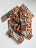
For the connections I make my own braided copper terminals as shown in the photo (connections between LiFePO4 cells), which are tightened to the greatest possible torque. It is a bit more work, but this way I am sure that the connections are perfect and that contact resistance is minimal.
 

Attachments

  • IMG_20210315_095930.jpg
    IMG_20210315_095930.jpg
    1.3 MB · Views: 31
Do you have the converters interface in the B pillar (UK drivers side).
As I understand it, as part of the option for that interface it includes an upgraded alternator
That interface provides a 50A 12v connection as well as D+ signal (0v on active)
 
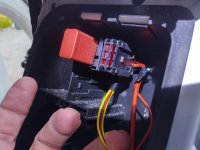
Hello BurntMarmite, thanks. The van is LHD. Down in the B style I found this, a fuse and a relay. Is that what you had in mind? See picture.
 

Attachments

  • IMG_20220220_180845_HDR.jpg
    IMG_20220220_180845_HDR.jpg
    3.2 MB · Views: 126
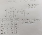
That is different indeed. Just to be sure, I measured all Voltages and can conclude there is nothing that can be used.
 

Attachments

  • 2022-02-22_17-07.jpg
    2022-02-22_17-07.jpg
    78 KB · Views: 38
That is different indeed. Just to be sure, I measured all Voltages and can conclude there is nothing that can be used.
Just to annoy you, sorry....
Even the official coverters socket can't be checked with a meter.....
The D+ signal is ECU controlled and "floats" and drawn to 0v when engine running
All good, but on mine at least, I got zero out of the port - it was floating even when engine running. But, as soon as I used it as an earth for a relay coil it worked (as per MisterG blog) - but testing on the multimeter wasn't able to confirm it was 0v..... Caused me a bit of grief till someone told me to just stick it relay earth on it..... (whilst other end of coil had power)

Yours looks different of course, so don't worry too much
 
To find the D+ I just used a small 12v test bulb (in a screwdriver)
One side connected to 12v positive
The other side connected to the D+
Then the light comes on when the engine is running
 
To find the D+ I just used a small 12v test bulb (in a screwdriver)
One side connected to 12v positive
The other side connected to the D+
Then the light comes on when the engine is running
I'll keep searching... Using this method was enough to exclude the B-style location without the optional electronics.
 
Back
Top