Tuning Installing a Prosport JDM Boost gauge on 2018 595 Comp

Currently reading:
Tuning Installing a Prosport JDM Boost gauge on 2018 595 Comp

Ramg

New member
Joined
Nov 28, 2021
Messages
12
Points
3
Location
ISRAEL
Hi Everyone
I want to install an after market boost gauge (the prosport JDM series).
I have a 2018 595 Comp with the T-Jet engine.
Anyone has experience with this gauge or replacing the boost guage in general? any instructions video or something?
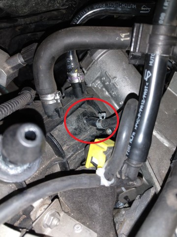
if not as I understand the Boost sensor that comes with the Guage need to be connected with a "T" Fitting on the intake vacuum line (better then the boost controller line as it can read also negative), can anyone guide me to the location of this line? if possible with a picture that would be amazing.
Thanks
 
I've heard of this being done on an Abarth, weirdly on a Subaru forum. Sadly the person concerned has disappeared so I can't ask them how to do it but I'm very interested to know myself...

Followed.

BTW I've no idea if the same applies to the Abarth but certainly on Subarus the best place to put it is in the boost line prior to the boot control solenoid - it's useful being able to see negative as well as positive boost since it gives you a good idea if there are any induction leaks, etc.
 
Last edited:
I've heard of this being done on an Abarth, weirdly on a Subaru forum. Sadly the person concerned has disappeared so I can't ask them how to do it but I'm very interested to know myself...

Followed.

BTW I've no idea if the same applies to the Abarth but certainly on Subarus the best place to put it is in the boost line prior to the boot control solenoid - it's useful being able to see negative as well as positive boost since it gives you a good idea if there are any induction leaks, etc.
Thanks a lot friend, lets wait maybe someone can help us
 
I'll be trying shortly once I've done the other upgrades I need to do, so if nobody responds within a week or so I'll post a link to my project so you can see how I get on installing a small digital gauge (and getting rid of the Fiat / Lego boost gauge)
 
I'll be trying shortly once I've done the other upgrades I need to do, so if nobody responds within a week or so I'll post a link to my project so you can see how I get on installing a small digital gauge (and getting rid of the Fiat / Lego boost gauge)
That will be amazing, thanks a lot my friend, do you have the Multiair or T-Jet engine?
 
Mine's an European type one, so would have the T-Jet, same as yours. Only difference is yours will have the Garrett turbo whereas I've got the IHI (missed out on the Garrett by 6 months)
Your next MOD ;), I guess it will be the same from piping POV, waiting for your update, thanks a lot my friend
 
Took me a time to fit since I needed to find somewhere to route the boost gauge wiring without drilling a hole in the bulkhead; turns out there's just enough room inside the grommet the windscreen washer hose goes through to push through a couple of wires, , and they can then be easily picked up if the parcel shelf in front of the BCU / fusebox is removed (think it's a glovebox on facelifts).

Once I'd got that sorted I tried a couple of locations for the boost sensor; installing it near the inlet was pointless (as expected) and there's nowhere to install it near the MAP sensor so the only other location available without drilling a hole in the inlet manifold is the fuel pressure regulator pipe:

Q8Kpef.jpg


Note - since any leaks could affect fuel pressure (which could lead to detonation!) make sure you use good quality hose, use an electronic boost sensor rather than an analogue one (pipe would be too long and may chafe where it goes through bulkhead) and keep the pipe run as short as possible. Also be very careful if you do fit it here - the connector on the manifold is plastic, and the hose may go a bit stiff with age, so if you pull the hose too hard it might snap the connector off the manifold, and Superglue won't help much fixing it...! So best to cut that pipe laterally with a Stanley knife rather than taking a risk if it doesn't come off easily.
 
Last edited:
Took me a time to fit since I needed to find somewhere to route the boost gauge wiring without drilling a hole in the bulkhead; turns out there's just enough room inside the grommet the windscreen washer hose goes through to push through a couple of wires, , and they can then be easily picked up if the parcel shelf in front of the BCU / fusebox is removed (think it's a glovebox on facelifts).

Once I'd got that sorted I tried a couple of locations for the boost sensor; installing it near the inlet was pointless (as expected) and there's nowhere to install it near the MAP sensor so the only other location available without drilling a hole in the inlet manifold is the fuel pressure regulator pipe:

Q8Kpef.jpg


Note - since any leaks could affect fuel pressure (which could lead to detonation!) make sure you use good quality hose, use an electronic boost sensor rather than an analogue one (pipe would be too long and may chafe where it goes through bulkhead) and keep the pipe run as short as possible. Also be very careful if you do fit it here - the connector on the manifold is plastic, and the hose may go a bit stiff with age, so if you pull the hose too hard it might snap the connector off the manifold, and Superglue won't help much fixing it...! So best to cut that pipe laterally with a Stanley knife rather than taking a risk if it doesn't come off easily.
Thanks a lot my friend
 
Back
Top