Technical Fiat Ducato 1985 XN1T Electricity and Generator issues

Currently reading:
Technical Fiat Ducato 1985 XN1T Electricity and Generator issues

Shibbiscus

New member
Joined
Jul 10, 2025
Messages
5
Points
1
Location
Skåne
Hi!
So me and my partner have had our fiat ducato from 1985 for 2 months, learning alot but got som issue with the generator not getting enough signal to start charging.
We have done a lot of searching and fixing to get it right but nothing is working.
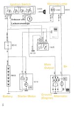
Wondering if anyone has access to an electricity diagram for this caravan?
Also wondering if anyone has eny experience or expertise that could help us out by answering on some more complex questions about our situation.

We have tried a testcabel from the battery to DF stift to see that the generator is charging the battery if we give it enough power to starr charging which it did.
So we started looking more at the electricity.
What happened next was we changed two relays in the glove compartment which we guessed might have something to do with it. Didnt change much. We guessed the lamp in the instrumentpanel might have been the issue as the DF cabel only got 6v but when we changed the lamp it got 9.6v. Which helped it start up twice but then didnt work again.

This all started when we tried the fridge for the first time while driving on the car battery. So maybe we ****ed some circuit up while doing that as we are noobs and when the fridge stopped working while driving 4h (it worked at the beginning). We tejped down the fridge button on the fuse box when it stopped working as chat gpt said it should be pressed down. (feel stupid now to have trusted that)..

Last thing we did was run a new cabel outside of the normal circuit, from a fuse that goes on ignition to an external lamp and then to DF on the generator.
But now I think it might have been on the wrong poles of the lamp because after this, the normal DF cable gives 0 energy, before it was 9.6v...

Did we **** up bad?
Did we break something even more? 😭

Please help us🙏❤️
 
Model
Fiat ducato XN1T
Year
1985
It is a very simple system on a 1985 vehicle.

The generator is excited by a very small current via the charge bulb(It has to be a bulb of correct watts and volts) when generator starts working the charge bulb has battery voltage on both wires and so goes out.

If charge bulb does not light key on engine not running , fault with wiring, fault with bulb, fault with generator.

I can't help with fridge .....but it is 30 years old so could be faulty-disconnect until generator problem fixed.
 
I do not know where to start with your problems. As @jackwhoo has said the basc circuit is really quite simple.

Perhaps we start at the begining when your alternator was not starting to charge. Here are some possible reasons.

1. Worn or sticking alternator brushes.
2. Faulty alternator regulator.
3. Too many additional relays etc connected to the DF (D+) point in the circuit. These could be connected anywhere between the alternator and the warning bulb.
4. Alternator belt too slack, and slipping as the alternator starts to generate electrical power.

My own measurement for the alternator field resistance on a 1990 Talbot Express, which is a similar vehicle, was 3.7 Ohms. This suggests a possible alternator field (rotor) current of about 3A at 12V. I do not see how connecting a slightly larger bulb, than the typical warning bulb could cause damage to the alternator circuit.

If your initial voltage reading of 6V at the D+ point was with the alternator stationary, I think that is too high. Most of the voltage should be across the bulb with only a small fraction across the alternator field. The situation reverses when the alternator is generating. Going back to my thinking that the 6V was too high, that could be an indication that there was a fault in the alternator field circuit. See points 1 & 2 above.

@Anthony489 any thoughts?
Thank you for your replies guys!
It helps.
Now we are pretty sure the generator is broken so we have got a new one soon that we will switch to.
🙏
 
Hello Shibbiscus

I only have a poor translation of an unofficial German manual for early X230 Ducatos. I have cleaned this up and added some annotations in yellow. The alternator arrangement is very simple. The main charging output of the alternator (Sometimes called B+) has the larger terminal and the thicker cable. It connects to the Battery positive with no relay contacts or switches. The D+ terminal of the alternator has the smaller terminal. When the engine is stopped but the ignition key is turned, a small current flows through the warning lamp, which lights up. The small current also excites the field winding, just enough to allow the alternator to produce an output as soon as the engine turns. After that, the alternator provides its own field current and the voltage at the D+ terminal rises to about the same as the main output. The warning lamp now has about 12 to 14 volts on both its terminals, so it stops lighting up. Finally, there is a ground connection to the Alternator using the fixing bolts to the engine metal. This metal then joins to battery negative via a cable.

Some motorhomes "borrow" the D+ feed to also drive a relay coil. The relay contacts can be used to switch auxiliary equipment that must only work when the engine is running and the alternator is charging. This "borrowing" is permissible provided the relay coil only needs a very small current. If too much current is drawn from D+ (for example someone adds extra relay coils or other items) the circuit will not work properly.

I hope your new alternator works well

Do not believe anything written by AI without checking. Garbage in, garbage out !
 

Attachments

  • X230 Ducato Starter and Charging.jpg
    X230 Ducato Starter and Charging.jpg
    113.7 KB · Views: 10
To avoid any confusion may I draw attention to a typographical error in the above diagram kindly prepared and posted by @Anthony489., in the previous post.
Near the lower RHS corner of the diagram it should read D+, instead of the B+ shown on the diagram. The correctly labelled main output is B+.

"He who makes no mistakes makes nothing."
 
Hello Shibbiscus

I only have a poor translation of an unofficial German manual for early X230 Ducatos. I have cleaned this up and added some annotations in yellow. The alternator arrangement is very simple. The main charging output of the alternator (Sometimes called B+) has the larger terminal and the thicker cable. It connects to the Battery positive with no relay contacts or switches. The D+ terminal of the alternator has the smaller terminal. When the engine is stopped but the ignition key is turned, a small current flows through the warning lamp, which lights up. The small current also excites the field winding, just enough to allow the alternator to produce an output as soon as the engine turns. After that, the alternator provides its own field current and the voltage at the D+ terminal rises to about the same as the main output. The warning lamp now has about 12 to 14 volts on both its terminals, so it stops lighting up. Finally, there is a ground connection to the Alternator using the fixing bolts to the engine metal. This metal then joins to battery negative via a cable.

Some motorhomes "borrow" the D+ feed to also drive a relay coil. The relay contacts can be used to switch auxiliary equipment that must only work when the engine is running and the alternator is charging. This "borrowing" is permissible provided the relay coil only needs a very small current. If too much current is drawn from D+ (for example someone adds extra relay coils or other items) the circuit will not work properly.

I hope your new alternator works well

Do not believe anything written by AI without checking. Garbage in, garbage out !
This is super helpful! Thank you tons!
Much love to you my friend.

Learning alot 🙏
100% with the AI...
Lesson learned.
 
To avoid any confusion may I draw attention to a typographical error in the above diagram kindly prepared and posted by @Anthony489., in the previous post.
Near the lower RHS corner of the diagram it should read D+, instead of the B+ shown on the diagram. The correctly labelled main output is B+.

"He who makes no mistakes makes nothing."
Thank you so much for contributing.
Helps us so much 🙏🙏🙏
 
Back
Top