Technical Ducato 244 elect. windows and locks not working

Currently reading:
Technical Ducato 244 elect. windows and locks not working

Joined
Apr 15, 2023
Messages
29
Points
86
Location
Åkersberga
Hi ! i bought a ducato 244 from 2006 with power windows/locks, since the fuse was not burned i assumed the door motors were broken, replaced them but still they are not working, when i put 12v on the motor the window goes up and there is also 12v on the (greenwhite wire) at the switch, anyone knows how to get it resolved, the same for the central locking system also this is not working...any help is much appricieated !

Also looking for an instruction video how to replace the fan motor i i had it almost disconnected by removing 4 bolts but couldnt get it out...
Not sure if this will work , but maybe if you have a full version of MES and leads you could try a "proxi alignment" to get the BCM Body Computer Module to recognise and/or test them.
 
I also have a 2006 Ducato x244, but I have not delved too deeply into the central locking and windows, the operation of which is controlled by a common control box. This box is sometimes called a "comfort module", and in my RHD vehicle it is behind the glove box. It is a classic "black box".

You mention a fuse not being blown, but which fuse? There are the 7.5A fuse F35 for the ignition controlled, control supply to the switches, and two 20A fuses, F47 & F48 for the window motors. See attached eLearn diagram E3050, and my own fuse box diagrams, which also show some items specific to my vehicle.

You have not mentioned any specific problem with the central locking, so I am unable to make specific suggestions. Diagram E3040 attached. Comments and annotations are mine.

To assist others please post what you find on this thread.
 

Attachments

  • eLearn E3050 Electric Windows.pdf
    87.5 KB · Views: 89
  • eLearn E3040 Central Locking.pdf
    107.1 KB · Views: 75
  • Fiat Wiring Colour Codes.pdf
    70.1 KB · Views: 82
absolutly i will check this and revert back - thank you very much for the files, the central locking simple doesnt work at all - will revert back on this aswell.
 
I also have a 2006 Ducato x244, but I have not delved too deeply into the central locking and windows, the operation of which is controlled by a common control box. This box is sometimes called a "comfort module", and in my RHD vehicle it is behind the glove box. It is a classic "black box".

You mention a fuse not being blown, but which fuse? There are the 7.5A fuse F35 for the ignition controlled, control supply to the switches, and two 20A fuses, F47 & F48 for the window motors. See attached eLearn diagram E3050, and my own fuse box diagrams, which also show some items specific to my vehicle.

You have not mentioned any specific problem with the central locking, so I am unable to make specific suggestions. Diagram E3040 attached. Comments and annotations are mine.

To assist others please post what you find on this thread.
Yes I think what I call a BCM you know as a "comfort module" I think with CanBus systems the BCM and ECU control many operations on modern vehicles which is great only while they keep working!:(
 
@bugsymike, I suppose you could call it a Body Control Module, but I have always understood that BCM referred to a canbus node, which controlled many more items than the central locking, and electric windows. The ABI unit on the x244 only controls those two functions. I suspect that it contains several small relays and electronic current detection devices to detect end of travel for the lock and window motors. Following the principle if it ain't brokre don't fix it, I have left it alone. The nearest that I have ventured electrically, was to add an additional lock/unlock switch on the dash, and push button controlled and timed control supply for the windows.
 
@bugsymike, I suppose you could call it a Body Control Module, but I have always understood that BCM referred to a canbus node, which controlled many more items than the central locking, and electric windows. The ABI unit on the x244 only controls those two functions. I suspect that it contains several small relays and electronic current detection devices to detect end of travel for the lock and window motors. Following the principle if it ain't brokre don't fix it, I have left it alone. The nearest that I have ventured electrically, was to add an additional lock/unlock switch on the dash, and push button controlled and timed control supply for the windows.
My knowledge is limited experience of the BCM on a daughters Punto Evo where a previous owners "repair" of a seat sensor damaged the BCM which I replaced and then had to run the "proxi alignment " program to get all the different airbag and other modules to talk to each other using a Snap On Zeus diagnostic tool that I was lucky to have access to.
I thought the "comfort module" was just a different name for the BCM, so from what you are saying it is a earlier more basic unit.
To be be honest modern ECU /Canbus etc electronics are something at my age I am struggling to get a basic grasp of, fortunately I have retired so don't need to invest in the latest technology to keep my customers on the road anymore.
When still working I tried to gain some knowledge as I found, like the early days of PCs there was lots of "experts" who talked down to you , charged the earth and in reality knew very little more than I did.:(
I would like to learn more but testing Canbus and modules etc . but it needs at least a dual channel oscilloscope and ideally a good technical course on the specifics as a starting point I understand.
 
OK all fuses are ok, the motors work on both sides with direct 12v so i ordered new switches ..hope this is the issue !
@sliderr ,

I missed your post quoted above. I would not have suggested such a course of action before further investigation.

The ABI, or "Comfort Module", otherwise the central locking and windows controller, is used by both central locking, and electric windows.
If it is unplugged or missing, that would explain your problems, with both systems not working.

As a minimum please try to confirm that the modle is present, and connected.

As previosly stated it is behind the glovebox on my RHD vehicle.

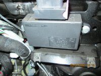
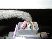
The unit shown in the attached photos, matches those offered for sale on Ebay, including part number, but I have yet to match the wiring to the circuit diagrams.
 

Attachments

  • IMG_0351.JPG
    IMG_0351.JPG
    3.9 MB · Views: 68
  • Window & Lock Module.JPG
    Window & Lock Module.JPG
    2.7 MB · Views: 56
OK yes i have this module aswell and it is connected ! - but how to troubleshoot the module is the question, i ordered new switches when that is not the problem i can return them and order a new controlbox (do you have a partnumber for the this? i try to read the picture but i cant cleary read it)
Will revert back and thank you so much for your help!!
 
Last edited:
As requested the Fiat part number is 1346927080. Searching with that number on Ebay brings up several ofers of used and new components. See here.
That will give you some idea of cost.

As I said, I cannot relate the connections shown on the diagrams with the actual unit. The unit has 3 rows of 8 contacts A1 to A8, B1 to B8, & C1 to C8. Both locking and window diagrams have numbers higher than 8????? I can only assume that the diagrams generally available are early versions, and that the unit design was changed after the diagrams were made. There are several errors elsewhere in Fiat eLearn , but this is the largest discrepancy. It does make testing difficult. You would have to rely on wiring colours alone. If wishing to test I would start by confirming that ALL supplies and earth connections were present.

It may be worth noting that the door connectors D016A, and D017A are also common to both systems, but if disconnected each would only affect one door.

I hope that some of this helps.
 
This post contains affiliate links which may earn a commission at no additional cost to you.
It may be worth noting that the door connectors D016A, and D017A are also common to both systems, but if disconnected each would only affect one door.
@sliderr,
As an afterthought, those connectors also provide connections for the electrically operated door mirrors. If the mirrors are working, then connectors probably OK.
 
OK update - i replaced the the switches and the module but still no working locks and windows, on the 7.5 A fuses i have 12v but i am not getting 12v on the F47 & F48 .. any idea or next step to check? @Communicator
 
Last edited:
In a word yes. F47 & F48 are in the RH cab fusebox, B101, which is supplied from midi fuse F71 in the battery fusebox, B099. See attached eLearn drawing E1010-1. The text annotations are mine.

Do not work on the battery fusebox without first disconnecting the battery negative.

Fuse F71 is shown as 80A, and should be white in colour. If F71 is faulty, Why?? the adjacent brown 70A fuse has no cable attached (converters fuse) you could use it as a temporary replacement, but be careful.

My preffered tool for working on the midi fuses, is a 1/4" drive 8mm socket, with ratchet drive handle.
 

Attachments

  • eLearn E1010-1 B101 RH Cab Fusebox.pdf
    84.1 KB · Views: 76
Last edited:
And this one ia also rated at 58V. That is OK for a nominal 12V system. I am wondering if they are used in fixed solar panel installatiors, and that is the reason for quoting the higher voltage rating?
 
This post contains affiliate links which may earn a commission at no additional cost to you.
Spot on! it works now! i started with a 40a fuse since i couldnt buy the 80a yet but that will arrive, and guess what AC in the cabin also started to work Thank you so much for your help @Communicator
I am puzzled by your report. Is that additional AC in the rear of the vehicle? Cab AC is shown as being supplied from Engine Bay fusebox, B001. A coincidence perhaps.

The 80A fuse should not blow under normal operation, so consider the possibility of another fault. Sorry to sound pessimistic
 
Back
Top