

Hello All,
My 2003 Ducato (2.0 JTD) cranks but does not start. With the ignition key in the ON position (without starting the van) I hooked up the alligator clip of my test light to the negative battery terminal and probed the injector wires with the test light pin. There was no indication of a 12 volt power supply to any of the 4 injectors. Previous tests done in the same manner have always lit up the test light.
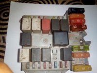
For this particular model, where is the +12v power to the injectors sourced from? I visually traced the wires coming from the injectors and they all seem to be hooked up directly to the ECU. I know that in most cases, the ECU completes the injector circuit on the ground side of the electrical set up. But does it also provide the positive 12v power in this particular model. If not, from where is the power sourced? Does anyone have a guide or diagram for the injector circuit? Please Help. Does the ECU have its own relay or fuse somewhere other than the main fuse tray?
Note: The in-tank pump primes and delivers fuel to the common rail high pressure pump. The fuses and relays in the engine compartment are all in good working condition. I am suspecting the ECU is damaged but there are no signs of electrical burns on it or anywhere else.
My 2003 Ducato (2.0 JTD) cranks but does not start. With the ignition key in the ON position (without starting the van) I hooked up the alligator clip of my test light to the negative battery terminal and probed the injector wires with the test light pin. There was no indication of a 12 volt power supply to any of the 4 injectors. Previous tests done in the same manner have always lit up the test light.
For this particular model, where is the +12v power to the injectors sourced from? I visually traced the wires coming from the injectors and they all seem to be hooked up directly to the ECU. I know that in most cases, the ECU completes the injector circuit on the ground side of the electrical set up. But does it also provide the positive 12v power in this particular model. If not, from where is the power sourced? Does anyone have a guide or diagram for the injector circuit? Please Help. Does the ECU have its own relay or fuse somewhere other than the main fuse tray?
Note: The in-tank pump primes and delivers fuel to the common rail high pressure pump. The fuses and relays in the engine compartment are all in good working condition. I am suspecting the ECU is damaged but there are no signs of electrical burns on it or anywhere else.
")