MIG welding gas supplies.

Currently reading:
MIG welding gas supplies.

Whilst I was pulling those books out of my tech books bookcase I thought this might interest those of you trying to get more deeply into electronic diagnostics. I'm still pretty low down on the learning curve myself but the more I "piddle" about with it all the more I realize how valuable it is to be able to graph outputs.

Those of us with MES (I also have VCDS for my VAG stuff) are spoilt here because MES allows graphing. The only problem is that using a scanner via the OBD port is showing you what the computer thinks is going on - so, sensor and it's wiring and it's connector(s) and anything else in that circuit so I've lately become very interested in Oscilloscopes because they allow you to break into a circuit and take readings at specific points which is much more useful.

When you start getting into this it doesn't take long to dawn on you that whatever you are using to produce the graph, it's only any use to you if you know what to look for and a large part of that is knowing what a healthy output from the component you are studying actually should look like.

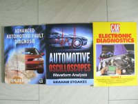
So how about these:
P1090328.JPG

Tom Denton's book I bought a few years ago and I refer to it a lot - you'll find it in a lot of public libraries.
Don't "sneer" at the Car mechanics booklet. It's one in a series they do and is a collection of some of the diagnostic features they do in every issue and contains tons of model specific detail (I bought this one because it has a 1.2 Punto in it and some VAG and Vauxhall stuff too). My latest indulgence is Graham Stoakes book on waveform analysis. I blew all my Christmas money on it and it hasn't failed to thrill! It's been the best so far by a long shot.

If you haven't tried a copy of Car Mechanics Magazine I would encourage you to give it a go. Those tech subjects towards the back of every issue are fascinating and very useful.
 
I always leave my gauge attached and backed off when not in use. That way I'll get a reading showing on the operating pressure gauge if the cylinder is leaking.

Rereading this I think it requires clarification? So, when you have finished working you would close the valve on the top of the cylinder. This should stop any gas getting out of the cylinder. However this valve may be damaged - I've only very occasionally come across this but it does happen.

So, to keep a check on this, after you've closed the cylinder valve don't touch the pressure setting and operate the trigger on the welder until no more gas comes out. This wastes a little gas but it's pretty insignificant.

So now there will be no gas pressure anywhere after the valve in the neck of the bottle. Now unscrew the pressure adjusting knob on the regulator until it's completely backed off. This takes the spring pressure off the diaphragm and stops any gas being able to get into the output side of the regulator body. It will not stop any gas leaking through the bottle valve from acting on the bottle contents gauge so if the valve is leaking the contents gauge will show pressure but the slacked off diaphragm will have closed the output side so no gas will be wasted and you'll know the bottle valve is leaking.

This will be a likely reason for a "new" bottle which is not up to the expected pressure when first connected and, if you want to make an issue of it - perhaps because you think the pressure is significantly down - of proving to the supplier that they need to give you another bottle.

I'm assuming you have a two gauge regulator. I've never used a one gauge regulator but I think in this case that the gauge shows regulated pressure only so probably you won't get the visual indication on the gauge but the regulator should still act to block gas leaking. - A bottle contents gauge will show pressure in thousands of psi whereas the operating pressure will be in tens of psi which will give you a clue.

Hmmm? not sure if that's clarified things or not? what do you think?
Jock
 
Last edited:
--------------------------
---------------------------

I think I've done everything possible on an Imp except rebuild a gearbox - I had 3 spare gearboxes and 5 engines at one time - I believe setting up the crown wheel/pinion clearance was difficult, with a capital D. King pin bushes were a regular feature I remember.

---------------------------

Hi Jock,

My late father went on the training course for the Hillman Imp around the time is was introduced, I always remember him telling me that with an al. alloy transaxle casing, you must set up the differential side-bearing pre-load a lot tighter than on a cast iron differential housing - the alloy expands as it heats up thereby reducing the bearing pre-load to 'normal' levels, as well as potentially altering the crownwheel/pinion mesh. The shim to set the pinion depth was determined by using special tools (dummy pinion shaft + pinion depth gauge).

He also was sent on the introductory course for the (then) new Rover 2000 (P6), I still have the factory workshop manuals etc. he was given.

Regards,

Al.
 
Last edited:
Rereading this I think it requires clarification? So, when you have finished working you would close the valve on the top of the cylinder. This should stop any gas getting out of the cylinder. However this valve may be damaged - I've only very occasionally come across this but it does happen.

So, to keep a check on this, after you've closed the cylinder valve don't touch the pressure setting and operate the trigger on the welder until no more gas comes out. This wastes a little gas but it's pretty insignificant.

So now there will be no gas pressure anywhere after the valve in the neck of the bottle. Now unscrew the pressure adjusting knob on the regulator until it's completely backed off. This takes the spring pressure off the diaphragm and stops any gas being able to get into the output side of the regulator body. It will not stop any gas leaking through the bottle valve from acting on the bottle contents gauge so if the valve is leaking the contents gauge will show pressure but the slacked off diaphragm will have closed the output side so no gas will be wasted and you'll know the bottle valve is leaking.

This will be a likely reason for a "new" bottle which is not up to the expected pressure when first connected and, if you want to make an issue of it - perhaps because you think the pressure is significantly down - of proving to the supplier that they need to give you another bottle.

I'm assuming you have a two gauge regulator. I've never used a one gauge regulator but I think in this case that the gauge shows regulated pressure only so probably you won't get the visual indication on the gauge but the regulator should still act to block gas leaking. - A bottle contents gauge will show pressure in thousands of psi whereas the operating pressure will be in tens of psi which will give you a clue.

Hmmm? not sure if that's clarified things or not? what do you think?
Jock

Hi Jock,

^^ Exactly as I was taught to do it. Although I never saw anyone else do this in any of the workshops I worked in.
Same as I never saw anyone back-off the adjustment on a torque wrench after they had finished using it. :bang:
(I brought my own one in and used it instead...).

Regards,

Al.
 
I always remember him telling me that with an al. alloy transaxle casing, you must set up the differential side-bearing pre-load a lot tighter than on a cast iron differential housing - the alloy expands as it heats up thereby reducing the bearing pre-load to 'normal' levels, as well as potentially altering the crownwheel/pinion mesh. The shim to set the pinion depth was determined by using special tools (dummy pinion shaft + pinion depth gauge).

He also was sent on the introductory course for the (then) new Rover 2000 (P6), I still have the factory workshop manuals etc. he was given.

Regards,

Al.

'Moring Al.

Probably not that bad to do then if you had access to the tools? Which, of course I didn't. Would have been interesting to see how it was done though.

We saw a lot more Triumph 2000, 2500 and the occasional 2.5PI (that fuel system was "interesting") than we ever saw of the Rovers. I remember some really weird things about them though like the difficulty of doing the tracking due to the way the steering was laid out and I remember one terrible job which came in with a creaking noise from the back. Turned out to be that the rubber bellows on the sliding rear axle (that was another very wierd idea?) had perished allowing the whole thing to corrode internally. I remember that customer looking shocked with the size of the bill for that one!

Both cars were a nice drive but I liked the sound of the Triumph's straight six - until they dropped the Buick V8 in the Rover anyway.
 
Same as I never saw anyone back-off the adjustment on a torque wrench after they had finished using it. :bang:
(I brought my own one in and used it instead...).

Regards,

Al.

Oh yes, not backing off the shop torque wrench before handing it back to the storeman? virtually a hanging offence according to our boss!

I've always been very interested in torque wrenches (I currently own 5) and shortly after I started posting on the forum I posted this:
https://www.fiatforum.com/grande-punto/454782-torque-wrench-calibration.html?454782=#post4299678
My post is the last one (at this time) in the thread. I would not claim that what I'm doing is as accurate as a "proper" calibration but it seems to work for me as a check. If calibration is then indicated the problem is you don't have any of the bits and pieces needed so handing it over to a specialist to do it would be the best option. Anyway I hope you find it interesting.

I didn't seem to have yet worked out how to post pictures when I did that so you might like this:

P1090329.JPG

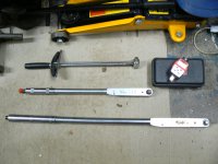
It shows my original, free with socket set purchase, "bendy beam" wrench. At the time I thought it was the bee's knees but then, mostly due to it's having been free, I lost faith in it thinking that such a simple device couldn't possibly be a rival for the Britool. Then later, when I did the calibration testing in the post I mention above, it turned out to be actually really quite accurate! I've since, with all the trips to the US when my daughter and family lived there, and especially the friendship I've formed with her nieghbour who is doing a floor up restoration of a MK1 Corvette, learned that the Yanks are really into beam type wrenches - even Snap On still make them - and you quite often see them in workshops over there. (they are a bit more "De Luxe" compared to my old friend though). Also shown is my original Britool and "Big Bertha" the one I got in pieces in a box. I've "fiddled about" quite a bit with Bertha and filed up mild steel washers to achieve an adjustment. In fact she gives quite good readings now, but with the washers being "soft" mild steel, not "hard" like a proper shim, I don't think it will hold calibration. One day maybe I'll try to get the right shims but I'm getting on just fine with the electronic adaptor - shown top right - so mending Bertha is of academic interest only.

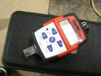
Here's a bigger picture of the adaptor which, by the way, runs on two CR 2032 button cells which are a very common size and available pretty much everywhere. Impressively, I'm still on the original set of, Sony branded, ones:

P1090330.JPG

Kind regards
Jock

PS. I'm still regularly making the Panini Pizza slices but I've modified the recipe a bit and green olives now feature strongly. A regular Saturday night treat for us!
 
Last edited:
'Moring Al.

Probably not that bad to do then if you had access to the tools? Which, of course I didn't. Would have been interesting to see how it was done though.

We saw a lot more Triumph 2000, 2500 and the occasional 2.5PI (that fuel system was "interesting") than we ever saw of the Rovers. I remember some really weird things about them though like the difficulty of doing the tracking due to the way the steering was laid out and I remember one terrible job which came in with a creaking noise from the back. Turned out to be that the rubber bellows on the sliding rear axle (that was another very wierd idea?) had perished allowing the whole thing to corrode internally. I remember that customer looking shocked with the size of the bill for that one!

Both cars were a nice drive but I liked the sound of the Triumph's straight six - until they dropped the Buick V8 in the Rover anyway.

Hi Jock,

Often, in the workshop in which I worked, these special tools had 'gone missing', so often had to just re-use the existing pinion depth shim and hope for the best - this is usually fine if the original crown-wheel and pinion are being re-used and just new pinion bearings are being fitted (these bearings are very accurately made, so their dimensions and therefore the pinion depth 'should' remain unchanged).

My dad loved the sound of a straight 6 in full flight. He couldn't aspire to a Rover P6 (similar story to your's - wife +kids + mortgage etc....) but he did have a couple of Vitesse's, both 1600's. He fabricated a 6 branch exhaust manifold and 3 siamesed inlets to take 3 x 1 1/2" S.U.'s. - he couldn't afford the S.A.H. Tuning offering - it went great, but then, he had been a Race Car Mechanic in his earlier years...

Re:- The Triumph P.I system, I still have my dad's factory info describing the operation, set-up and adjustment of this fuel system, I don't know if ever went on a training course for this system or had just acquired the tech. info. I believe this system was actually pretty good but acquired a bad reputation mainly because of high-pressure fuel pump issues (nowadays easily solved). (back in the day, one of the suggested modifications was to circulate the fuel through a coiled pipe surrounding the fuel pump in an attempt to keep the pump cool).

The Rover P6 was a very innovative design, in many ways.
The rear suspension 'de-Dion' system was unique in that the 'tube' was in 2 parts that could telescope (ref. - your torn rubber bellows), thereby avoiding the need for sliding splines in the driveshaft, with consequent stiction under drive or braking torque while still keeping the wheels vertical and parallel in relation to the body. It also had inboard rear disc brakes fitted (just like a Jaguar :) ).

The P6 front suspension design, i.e. a bellcrank which conveyed the vertical motion of the wheel to a fore-and-aft horizontally mounted spring. (I wonder where F1 etc, got the inspiration for their inboard horizontally mounted suspension springs?....).This suspension design was chosen to allow as much width for the engine compartment as possible so that Rover's Gas Turbine engine could be fitted. This Gas Turbine engine was never used in production but later allowed the Rover V-8 to be fitted.

Regards,

Al.
 
Hi Jock,

I read your post on torque wrenches and their testing, also your earlier post you linked.

I (briefly) worked on Jet Engine Fuel Systems and while there I took advantage of the in-workshop torque wrench testing equipment and tested/adjusted all of my personal ones myself (none were out by much, but I wanted to get them to be as accurate as possible). Most torque wrenches (incl Britool) are accurate to +/- 4%, good (expensive!) ones might be +/- 2%. Everyone there used Snap-On brand, the in-house one's were regularly checked and date-stickered as such, anyone wanting to use their personal torque wrench(s) had to first submit it(them) for an accuracy check and have it(them) stickered and re-tested at set intervals. No current sticky, no usey!!!

I've seen mention in some of the car mags of those electronic torque adaptors being used to check the accuracy of a torque wrench, also another torque wrench being used along with an adaptor to check same.

Britool used to sell torque wrench calibration tester equipment. I wonder if
www.expert-by-facom.co.uk stock those fine adjustment shims that you require.They still supply the Britool Classic Torque Wrench and say the accuracy is +/- 4%.
Their website also lists www.tool-cal.co.uk as a service agent for the Britool Classic Torque Wrench in the U.K. (no doubt at a price...).

Iirc, some of the mobile tool vans e.g. Snap-On (tool trucks as they call them in the U.S.) used to carry a torque wrench tester on their vans, so you could have a quick check carried out on the accuracy of your torque wrench, presumably at nil/low cost? For anyone wanting to have their torque wrench accuracy checked, it might be worth asking around to see if this service is available in your area?

Regards,

Al.
 
Hi Jock,

Often, in the workshop in which I worked, these special tools had 'gone missing', so often had to just re-use the existing pinion depth shim and hope for the best - this is usually fine if the original crown-wheel and pinion are being re-used and just new pinion bearings are being fitted (these bearings are very accurately made, so their dimensions and therefore the pinion depth 'should' remain unchanged).

My dad loved the sound of a straight 6 in full flight. He couldn't aspire to a Rover P6 (similar story to your's - wife +kids + mortgage etc....) but he did have a couple of Vitesse's, both 1600's. He fabricated a 6 branch exhaust manifold and 3 siamesed inlets to take 3 x 1 1/2" S.U.'s. - he couldn't afford the S.A.H. Tuning offering - it went great, but then, he had been a Race Car Mechanic in his earlier years...

Re:- The Triumph P.I system, I still have my dad's factory info describing the operation, set-up and adjustment of this fuel system, I don't know if ever went on a training course for this system or had just acquired the tech. info. I believe this system was actually pretty good but acquired a bad reputation mainly because of high-pressure fuel pump issues (nowadays easily solved). (back in the day, one of the suggested modifications was to circulate the fuel through a coiled pipe surrounding the fuel pump in an attempt to keep the pump cool).

The Rover P6 was a very innovative design, in many ways.
The rear suspension 'de-Dion' system was unique in that the 'tube' was in 2 parts that could telescope (ref. - your torn rubber bellows), thereby avoiding the need for sliding splines in the driveshaft, with consequent stiction under drive or braking torque while still keeping the wheels vertical and parallel in relation to the body. It also had inboard rear disc brakes fitted (just like a Jaguar :) ).

The P6 front suspension design, i.e. a bellcrank which conveyed the vertical motion of the wheel to a fore-and-aft horizontally mounted spring. (I wonder where F1 etc, got the inspiration for their inboard horizontally mounted suspension springs?....).This suspension design was chosen to allow as much width for the engine compartment as possible so that Rover's Gas Turbine engine could be fitted. This Gas Turbine engine was never used in production but later allowed the Rover V-8 to be fitted.

Regards,

Al.
G'Day Al.

Always annoying when just one small part of a special tool kit is missing. Tools going missing was always a problem in the training environment. Soon after I started as a trainer (lecturer would be too grand a title) I decided to appoint a "storeman", Always one of the chaps who would be finishing his course within a month or so, to control issue and recovery of special and high value tools. It worked very well indeed - especially if the "storeman" was a bit of a bruiser!

Your Dad had a 1600 Vitesse? (or two) what a coincidence. When I left college and went to work for Firestone Racing I had my shabby, but reliable, little 997cc Anglia. Racing Division had it's own car park and the first day I rolled up at work I slotted it in between a Reliant Scimitar saloon (a rare car even in it's day) and an E type Jag. There were plenty of other "interesting" cars parked too. As a young "virile" male I felt most inferior. I couldn't afford such exotica but when I heard of a Vitesse saloon for sale near home I just had to go and look at it. It was a two tone Olive Green job - the 1600's were all two tone I think? - Twin Strombergs, which surprised me. Don't know why but I expected to see SUs. It was in great condition. I bought it on the spot, without even consulting SWMBO but she was Ok with it. I agree the engine could really "Howl" when wound up, but the swing axle rear suspension always made rapid progress "interesting". I meant to fit a decamber spring to the rear but never got round to it because I was so busy working. I owned her for about 3 or 4 years and the only serious thing that went wrong was when she broke part of a tooth off her crownwheel. I was just pulling away - in a rather too spirited way - from the traffic lights in Camberley (we lived in Blackwater at that time) when she went "all sluggish" as if the brakes were seriously dragging. I stopped and had a good look round but could see nothing untoward. Continued on a bit and she drove fine - strange?. Then the traffic stopped me and as I started off again she went all sluggish again. As I lifted off the throttle there was a horrendously loud bang from the rear. I stopped and looked under the back to be greeted with a puddle of gear oil and more dripping down. I was only a mile from home so I drove her home without any problem. In fact she ran absolutely normally but when I stripped her down - and boy were those long bolts difficult to get out - I found half a tooth missing from the crown wheel. It had wedged itself up the back of the casing between the casing and the crownwheel - which explains the "dragging" brakes effect - and blown a quite sizeable hole in the diff casing - which accounts for the big (and quite frightening) bang. Exit the broken piece of gear, chunk of case and most of the oil. I got a used diff from the local breakers and was soon back on the road again but it cured me of doing rapid take offs in first gear for ever! There have been two Heralds in the extended family in the past too and we frequently saw them in our workshop. The common problems I remember with them were rapid wearing plastic suspension bushings, Universal joints on the inner end of the rear driveshafts, and out of balance prop shafts. The prop shaft problem was a common one and, in the garage later in my career, we would only fit a complete exchange shaft as they would often vibrate if you tried to just do a joint. I also remember the boss having chats with customers about how rapidly the front tyres could be worn out if you frequently used it's astonishingly tight turning circle. I really loved that Vitesse, driven reasonably it was a quite rapid and comfortable drive. Very nice for our twice yearly visits back up to Scotland to visit our folks but it could have done with overdrive on the motorway.

We weren't allowed to touch the PI system. The boss had a "tame" specialist who would come in to do them. The only one I remember was a particularly gorgeous looking 2.5 PI sports TR6 which was in the workshop for at least a week whilst this chap tried to sort it out. No idea what he was doing but it was nice to have someone else to speak to at tea breaks.

Yes those Rovers were very different compared to the Triumph 2000 - which, of course was often the other car people were considering when it came to buying. I remember all those features of which you speak - that front spring arrangement was always a surprise the first time you saw it. Very very interesting what you have to say about the design being to accommodate the turbine - I remember the excitement around that experimental "car of the future". Of course drive shaft splines binding up under drive on axle shafts is much more of a problem than on a prop shaft due to the much greater torque being applied but I can't say I've ever found it a problem on standard road going vehicles and changing pads on inboard discs is often more of a "faff". Also not sure if keeping wheels vertical is actually desirable under cornering? multi link suspension allows controlled degrees of negative camber to be introduced with consequent advantages in how the tyre grips the road. I think it was a marginally more comfortable car to ride in though? I always thought the Triumph was a bit "wallowy"? - I believe there was a lot of trouble with corrosion on the alloy rear hubs of the Triumphs as they aged too, which made doing wheel bearings etc more difficult.

Always such interesting things we talk about Al, thanks so much. I'm doing this whilst waiting for my oldest boy to call round to borrow my electric drill. Wonder if I'll ever see it again?

As always, kindest regards
Jock
 
Hi Jock,

I read your post on torque wrenches and their testing, also your earlier post you linked.

I (briefly) worked on Jet Engine Fuel Systems and while there I took advantage of the in-workshop torque wrench testing equipment and tested/adjusted all of my personal ones myself (none were out by much, but I wanted to get them to be as accurate as possible). Most torque wrenches (incl Britool) are accurate to +/- 4%, good (expensive!) ones might be +/- 2%. Everyone there used Snap-On brand, the in-house one's were regularly checked and date-stickered as such, anyone wanting to use their personal torque wrench(s) had to first submit it(them) for an accuracy check and have it(them) stickered and re-tested at set intervals. No current sticky, no usey!!!

I've seen mention in some of the car mags of those electronic torque adaptors being used to check the accuracy of a torque wrench, also another torque wrench being used along with an adaptor to check same.

Britool used to sell torque wrench calibration tester equipment. I wonder if
www.expert-by-facom.co.uk stock those fine adjustment shims that you require.They still supply the Britool Classic Torque Wrench and say the accuracy is +/- 4%.
Their website also lists www.tool-cal.co.uk as a service agent for the Britool Classic Torque Wrench in the U.K. (no doubt at a price...).

Iirc, some of the mobile tool vans e.g. Snap-On (tool trucks as they call them in the U.S.) used to carry a torque wrench tester on their vans, so you could have a quick check carried out on the accuracy of your torque wrench, presumably at nil/low cost? For anyone wanting to have their torque wrench accuracy checked, it might be worth asking around to see if this service is available in your area?

Regards,

Al.
Hello again Al, He hasn't arrived yet so I'll keep going at this for now!

The world of Aircraft engineering is at a whole different level to the sort of "stuff" I do. My son in law works for a civilian (I think) organisation which helps the military with aircraft (better say no more than that) He works a lot with Fast Jets and he's occasionally managed to get permission for me to accompany him on base to see some of the less sensitive stuff he does. I find it absolutely fascinating. The standards to which they work and the quality of components and the finish on castings, turbine blades etc, etc, well, I could go on and on. Accountability too is something perhaps the motor trade could benefit from? I should have studied aeronautical engineering!

Thanks for the tip off regarding Facom. I think I'd clocked that they were still making "my" wrench - must look to see if they still do "Bertha" - but I never thought of contacting them. Thanks too for the info on the Snap On vans carrying a tester. I still have a number of friends, and sons of friends, working in the trade. I'll ask one of them to check that out for me and if they still carry a tester I'll see if I can avail myself of it. All my wrenches have been checked for years now either by putting them back to back with a wrench that's recently been calibrated or by using my electronic adaptor (which is "just" a strain gauge I think?). It would be very interesting to see how the readings vary. I have to say though that, being just road vehicles - as opposed to aircraft - as long as it's "very close" that'll do me fine. Haven't had anything come apart over the years.

'Till the next time then, regards
Jock
 
The world of Aircraft engineering is at a whole different level to the sort of "stuff" I do. My son in law works for a civilian (I think) organisation which helps the military with aircraft (better say no more than that) He works a lot with Fast Jets and he's occasionally managed to get permission for me to accompany him on base to see some of the less sensitive stuff he does. I find it absolutely fascinating. The standards to which they work and the quality of components and the finish on castings, turbine blades etc, etc, well, I could go on and on. Accountability too is something perhaps the motor trade could benefit from? I should have studied aeronautical engineering!
Jock

Well I used to work in the defence industry (civilian) designing electronic equipment for the military (tanks and aircraft) and even the design stages are very restricted by high quality components and procedures. You could only use "approved" components. The components were all traceable to their source materials/batches so should a problem later occur with the quality or reliability of any component all production units and where fitted could be hauled in for rework. Simple plated mechanical components were likewise traceable/track-able so if plate finish were a problem all components from the same batch could be tracked down.

Some of us young keen engineers used to complain/grumble to ourselves that our ingenuity and productivity was being serious hampered and also spoiling the fun of the job.

From day 1 your work would be tracked under a project management system with weekly time cards to filled out with hours and costs for each activity. (designing, parts ordering, spec writing, manual writing, testing etc.) The later you got into the design and testing stage the more your hands got tied. Come formal prototypes (A and B) these had to be built, tested and QAed by certified technicians etc. So when your prototype was delivered to you after build/ testing/validation to the documents you had written because of an issue that you could fix in 5 minutes (e.g. change a resistor value) you were not allowed to make that change. Lots of paperwork and then send the unit back round the cycle again.

I got a right *ollocking once because a unit failed during testing. The fault report form/paperwork came back with R9 (resistor 9) smokes. That was all. I sent it back with the question "What colour and smell was the smoke?"

My take was that the prototype testing technicians are supposed to be able to also do further diagnostic work and investigation at the "design level" and not just observer a component burning out.

For those not in the know in electronics over the years one can often characterise type and magnitude of fails by smell, smoke and even flames. :D
 
Back
Top