In the Panda '03 to '12 section I have been following and contributing to a very interesting thread "weird steering" in which I threatened to wheel out my home made tracking gauge. So, for your delectation and edification, here we go!
First thing to say is that we are talking only of front wheel "Toe" measurement/adjustment here. You may have heard it referred to as wheel alignment? Wheel alignment commonly includes the Toe setting, Camber angle and King Pin Inclination (a carry over from when vehicles had "King Pins") A proper wheel alignment procedure is complicated and only the brave, or incurably optimistic, would attempt to do it themselves! Find a specialist with a full laser aligning setup for this if I were you. But Toe settings can be quite accurately checked with a number of commercially available tools - try You Tube for some very interesting attempts. This is my attempt!
Prior to this there were two working prototypes which finally refined down to this one and, although it looks ridiculously simple and has no "bells or whistles" it has served me well for over 30 years. I use it on all the "family fleet vehicles" with great success.

Here it is disassembled. The two main horizontal tubes were pieces of steel pipe off cut left over from the steam heating system at my work when it was overhauled. (taken with my boss's permission) the larger diameter is about 1" od. The smaller about 3/4" od. These are very substantial pipes with a sidewall thickness of about 1/8". The smaller tube is a very close sliding fit inside the larger. I chose them for their rigidity, close sliding fit, and 'cos they were free! At each end there is tubing (steel electrical conduit) bent up at a little over 90 degrees with stops brazed to their ends such that the face of the stop is at 90 degrees to the main sliding tubes. The larger diameter tube, on the right in the picture, has a two legged foot which fits over it incorporating a locking turn screw allowing for adjustment (explanation to come) and the smaller tube, on the left, has a "pointer" on a sliding collar with locking turn screw allowing for adjustment (explanation to come)

Put it all together and you've got what you see in the first picture. The tool is readied for action by applying a length of masking tape to the left end of the large diameter sliding tube. By the way the sliding tubes are lightly greased to facilitate smooth use.
I'm primarily describing how my tool works in this description, so this is not attempting to describe how to adjust toe settings as such, but it is important to say that for this exercise to be meaningful a very thorough check of all the steering joints, suspension bushes and components, wheel bearings etc must be undertaken before starting as wear, excess movement or damage (ie a bent suspension arm) will make a nonsense of it. One thing many people miss though, and I've seen this many times where untrained or unspecialised staff are involved, is to check whether the wheel rims are "true" by which I mean are the rims undamaged. Damaged rims are common due to "Kerbing" and if a rim does not run "true" then you've no hope of doing this job accurately. Some say that readings can be taken from the tyre wall and they can but I don't think it's so accurate due to the curvature of the sidewall, compliance of the rubber and relatively uneven nature of the sidewall. To check this jack the car up so the wheel is just clear of the ground and can be rotated easily (so no gear selected. You did chock a rear wheel didn't you?) you need a fixed point placed very close to the rim so you can observe the gap between the rim and pointer as you rotate the wheel through a full revolution. I used a rule steadied on an axle stand and you'll need the wheel trim off too.

I like to mark the parts of the rim which do not rotate true with a chalk.

Now I know I cant use anywhere with the white chalk as a reference point so I will place it at either the top or bottom when doing my measurements as they need to be taken at 3 and 9 o'clock. Now go round and do the same to the other front wheel. Now let the car back down onto its wheels and run the car back and forwards over a few yards to settle the suspension back fully to it's normal running condition. Finish up by going forward and don't let the car run back as you want any forces acting on the suspension when traveling forward to be prevalent. Check also that none of your white chalk marks are at 3 or 9 o'clock. If you need to adjust the position slightly remember to only go forward! Oh yes, you need a nice surface to be doing this on too!
Now take the tracking tool and, using the adjustable foot, set it up so it's level with the center of the axle nut and lock off the turn screw. This must not now be loosened for the rest of the operation!
We now need a way of setting the stop on the other end to the same working height (this is critical as failing to make measurements at the same height will be meaningless due to the wheel camber.) This is very simple. A piece of wood cut to the same length does the job grand!

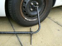
Now position the entire tool across the front of the car

with the stop on the end with the locked up foot against the front edge of the rim of the NSF wheel

and the stop on the free arm, now supported at the correct height by our piece of cut wood, against the front edge of the rim of the OSF wheel

Check carefully that that the stops are fully in contact with the wheel rims on both sides and now slide the adjustable pointer over the piece of masking tape you previously stuck to the large diameter slide tube and lock up its turn screw. this also must not now move for the rest of the operation. One last check to make sure the stops are snug against the wheel rims and, taking a sharp pencil, hold it at right angles to the large diameter tube (to avoid parallax errors) scribe a line against the pointer on the masking tape.

Now slide the whole tool under the car behind the front wheels and repeat the setup against the back of the rims. Making sure the height of the free end is correct using the wooden distance piece and that the stops are snug against the rims


Take the tool out from under the car and have a look at the pencil marks


The first mark I made, with the tool positioned in front of the wheels, is the mark on the right. You will see that there is a small distance (it's actually just under 3mm) to the second mark on it's left. Think about this for a minute. Ok this means the front edges of the two wheels are just under 3mm closer together than the back edges. So the front wheels are not rolling down the road parallel to one another but are "snowplowing" that is "Toed In". Mr Haynes tells me the ideal setting is parallel with a very small allowance of error, but not 3mm. So this explains why my front tyres are exhibiting the signs of too much toe in which I observed in the "weird steering" post. Correcting this is, I think, another story for another day as I'm going quite cross eyed after all this.
Here's a wee puzzle though, just to finish up with. When I removed the wheel studs off to get rid of the wheel trims I "lost" two of them for about a couple of minutes. Can you spot them?

First thing to say is that we are talking only of front wheel "Toe" measurement/adjustment here. You may have heard it referred to as wheel alignment? Wheel alignment commonly includes the Toe setting, Camber angle and King Pin Inclination (a carry over from when vehicles had "King Pins") A proper wheel alignment procedure is complicated and only the brave, or incurably optimistic, would attempt to do it themselves! Find a specialist with a full laser aligning setup for this if I were you. But Toe settings can be quite accurately checked with a number of commercially available tools - try You Tube for some very interesting attempts. This is my attempt!
Prior to this there were two working prototypes which finally refined down to this one and, although it looks ridiculously simple and has no "bells or whistles" it has served me well for over 30 years. I use it on all the "family fleet vehicles" with great success.
Here it is disassembled. The two main horizontal tubes were pieces of steel pipe off cut left over from the steam heating system at my work when it was overhauled. (taken with my boss's permission) the larger diameter is about 1" od. The smaller about 3/4" od. These are very substantial pipes with a sidewall thickness of about 1/8". The smaller tube is a very close sliding fit inside the larger. I chose them for their rigidity, close sliding fit, and 'cos they were free! At each end there is tubing (steel electrical conduit) bent up at a little over 90 degrees with stops brazed to their ends such that the face of the stop is at 90 degrees to the main sliding tubes. The larger diameter tube, on the right in the picture, has a two legged foot which fits over it incorporating a locking turn screw allowing for adjustment (explanation to come) and the smaller tube, on the left, has a "pointer" on a sliding collar with locking turn screw allowing for adjustment (explanation to come)
Put it all together and you've got what you see in the first picture. The tool is readied for action by applying a length of masking tape to the left end of the large diameter sliding tube. By the way the sliding tubes are lightly greased to facilitate smooth use.
I'm primarily describing how my tool works in this description, so this is not attempting to describe how to adjust toe settings as such, but it is important to say that for this exercise to be meaningful a very thorough check of all the steering joints, suspension bushes and components, wheel bearings etc must be undertaken before starting as wear, excess movement or damage (ie a bent suspension arm) will make a nonsense of it. One thing many people miss though, and I've seen this many times where untrained or unspecialised staff are involved, is to check whether the wheel rims are "true" by which I mean are the rims undamaged. Damaged rims are common due to "Kerbing" and if a rim does not run "true" then you've no hope of doing this job accurately. Some say that readings can be taken from the tyre wall and they can but I don't think it's so accurate due to the curvature of the sidewall, compliance of the rubber and relatively uneven nature of the sidewall. To check this jack the car up so the wheel is just clear of the ground and can be rotated easily (so no gear selected. You did chock a rear wheel didn't you?) you need a fixed point placed very close to the rim so you can observe the gap between the rim and pointer as you rotate the wheel through a full revolution. I used a rule steadied on an axle stand and you'll need the wheel trim off too.
I like to mark the parts of the rim which do not rotate true with a chalk.
Now I know I cant use anywhere with the white chalk as a reference point so I will place it at either the top or bottom when doing my measurements as they need to be taken at 3 and 9 o'clock. Now go round and do the same to the other front wheel. Now let the car back down onto its wheels and run the car back and forwards over a few yards to settle the suspension back fully to it's normal running condition. Finish up by going forward and don't let the car run back as you want any forces acting on the suspension when traveling forward to be prevalent. Check also that none of your white chalk marks are at 3 or 9 o'clock. If you need to adjust the position slightly remember to only go forward! Oh yes, you need a nice surface to be doing this on too!
Now take the tracking tool and, using the adjustable foot, set it up so it's level with the center of the axle nut and lock off the turn screw. This must not now be loosened for the rest of the operation!
We now need a way of setting the stop on the other end to the same working height (this is critical as failing to make measurements at the same height will be meaningless due to the wheel camber.) This is very simple. A piece of wood cut to the same length does the job grand!
Now position the entire tool across the front of the car
with the stop on the end with the locked up foot against the front edge of the rim of the NSF wheel
and the stop on the free arm, now supported at the correct height by our piece of cut wood, against the front edge of the rim of the OSF wheel
Check carefully that that the stops are fully in contact with the wheel rims on both sides and now slide the adjustable pointer over the piece of masking tape you previously stuck to the large diameter slide tube and lock up its turn screw. this also must not now move for the rest of the operation. One last check to make sure the stops are snug against the wheel rims and, taking a sharp pencil, hold it at right angles to the large diameter tube (to avoid parallax errors) scribe a line against the pointer on the masking tape.
Now slide the whole tool under the car behind the front wheels and repeat the setup against the back of the rims. Making sure the height of the free end is correct using the wooden distance piece and that the stops are snug against the rims
Take the tool out from under the car and have a look at the pencil marks
The first mark I made, with the tool positioned in front of the wheels, is the mark on the right. You will see that there is a small distance (it's actually just under 3mm) to the second mark on it's left. Think about this for a minute. Ok this means the front edges of the two wheels are just under 3mm closer together than the back edges. So the front wheels are not rolling down the road parallel to one another but are "snowplowing" that is "Toed In". Mr Haynes tells me the ideal setting is parallel with a very small allowance of error, but not 3mm. So this explains why my front tyres are exhibiting the signs of too much toe in which I observed in the "weird steering" post. Correcting this is, I think, another story for another day as I'm going quite cross eyed after all this.
Here's a wee puzzle though, just to finish up with. When I removed the wheel studs off to get rid of the wheel trims I "lost" two of them for about a couple of minutes. Can you spot them?