

You are using an out of date browser. It may not display this or other websites correctly.
You should upgrade or use an alternative browser.
You should upgrade or use an alternative browser.
Technical Timing belt change DIY
- Thread starter jsp
- Start date
Currently reading:
Technical Timing belt change DIY

- Joined
- Oct 26, 2005
- Messages
- 359
- Points
- 132
No personal experience of this job but there is a guide here:
https://www.fiatforum.com/stilo-guides/206576-how-change-1-6-timing-belt.html
https://www.fiatforum.com/stilo-guides/206576-how-change-1-6-timing-belt.html
First you rotate the crankshaft to set the piston from first cylinder in upper position.
This is the tdc.
Then block the crankshaft in this position.
After that use the camshafts locks tools.
Of course all these without the timming belt
This is the tdc.
Then block the crankshaft in this position.
After that use the camshafts locks tools.
Of course all these without the timming belt
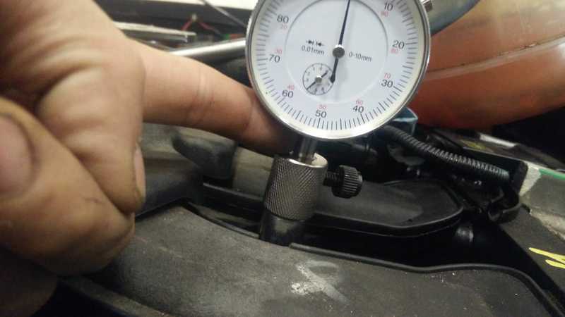
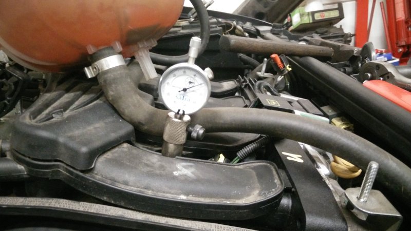
I cant set tdc. the dual gauge goes out of the tool if I put engine on tdc.
You really dont need this gauge.
Put a stick through spark plug hole and watch when it is in the higher position.
This crankshaft position is one you need to lock.
�� Nice to see these tools in "real life" personal images. I normally time the engine without any of these tools.
Not because I dont want to but it is not available in my country.
I believe the tools would make your job easier... or not.
But all you need to do is:
.1) Get the first piston to TDC
.a I normally use the oil dip stick and a tipex marker to do this(Tipex helps so u know if the piston by chance moved away from TDC while installing the belt)..
.b recently I just look at the dip stick and see when it stops going up and starts coming back down.
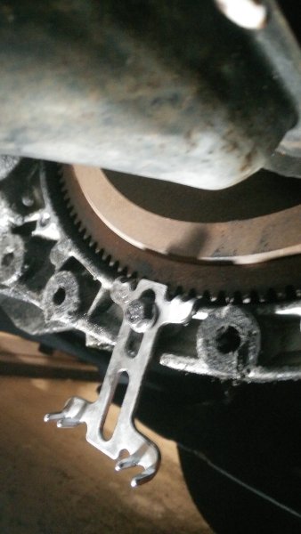
.c Most recently I just check the dot on the flywheel and align it to the crank sensor
.d You can use the dial guage and the locking tool for the crankshaft but I've never seen one used so I cant advice on how to use it
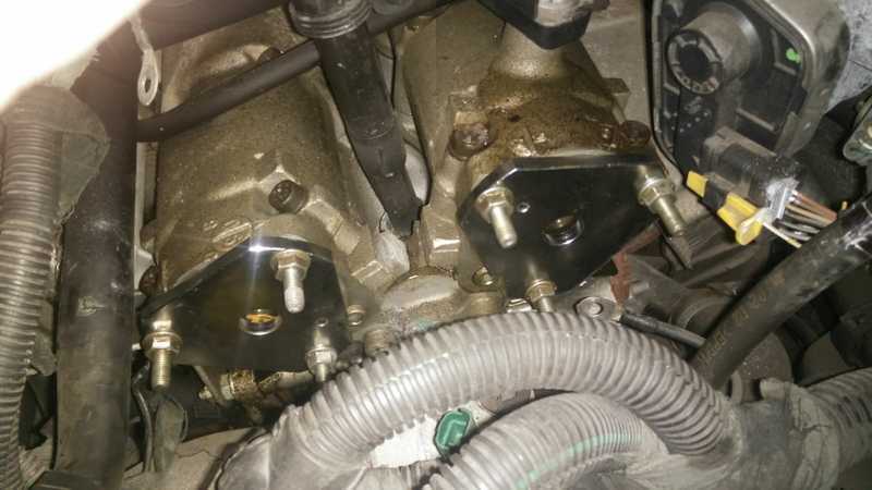
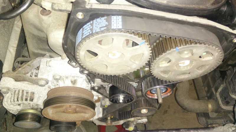
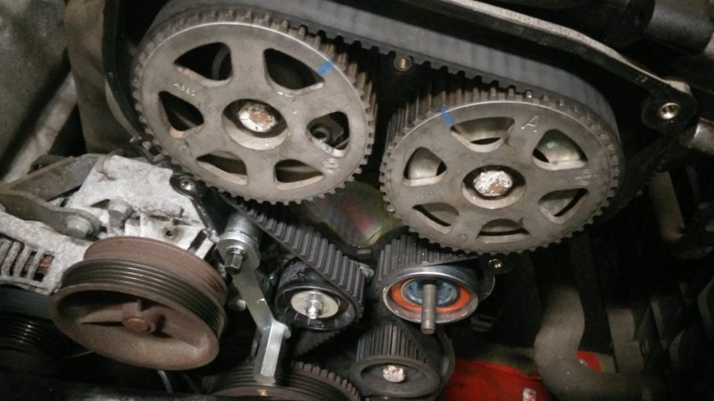
.2) Lock the camshaft with the tools
I just use some cut out paper diagram of the tool to check the cams are in correct position
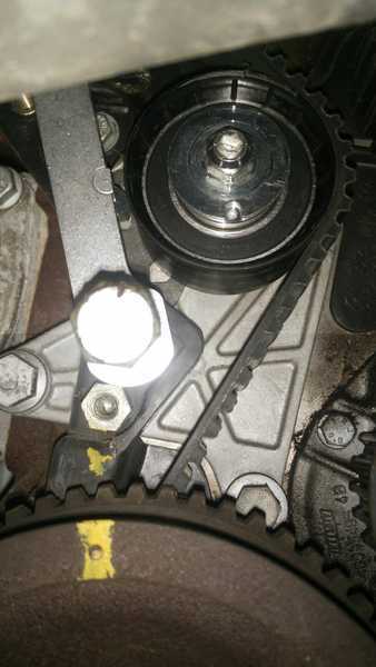
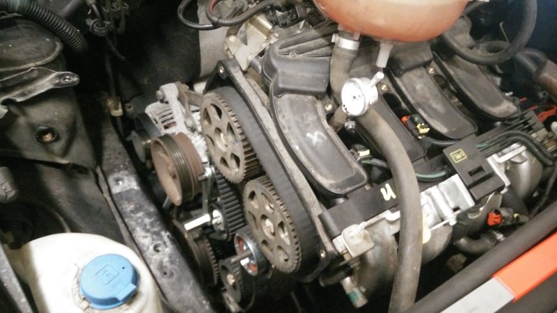
.3) Install belt
.4) Tension the belt with the tensioning instructions.
I have used different types of tensioners and each one had different mechanisms. But the common denominator is to the align whatever mark the tensioner has on it to wherever it is meant to align to, then tighten it.
.5) Remove all locks and turn over the engine by hand a couple of times then check if all marks are still aligned. If yes, you are good to go.
Not because I dont want to but it is not available in my country.
I believe the tools would make your job easier... or not.
But all you need to do is:
.1) Get the first piston to TDC
.a I normally use the oil dip stick and a tipex marker to do this(Tipex helps so u know if the piston by chance moved away from TDC while installing the belt)..
.b recently I just look at the dip stick and see when it stops going up and starts coming back down.
.c Most recently I just check the dot on the flywheel and align it to the crank sensor
.d You can use the dial guage and the locking tool for the crankshaft but I've never seen one used so I cant advice on how to use it
.2) Lock the camshaft with the tools
I just use some cut out paper diagram of the tool to check the cams are in correct position
.3) Install belt
.4) Tension the belt with the tensioning instructions.
I have used different types of tensioners and each one had different mechanisms. But the common denominator is to the align whatever mark the tensioner has on it to wherever it is meant to align to, then tighten it.
.5) Remove all locks and turn over the engine by hand a couple of times then check if all marks are still aligned. If yes, you are good to go.
Last edited:
I just use some cut out paper diagram to check the cams are in correct position
.
How do you do that ?
More detailed explanation.
How do you do that ?
More detailed explanation.
I guess that with no.1 cyliner at TDC and the cam-belt still on the engine, he takes a bit of paper, sticks it on the inlet cam-shaft lobe at no.2 cylinder to get the "shape" the lobe makes against the face of the head... then cuts out the shape so that the cut-out fits onto the cam-shaft lobe.
You'd need another one for the exhaust cam.
As you're fitting the new belt you can check the paper cut-out shape still fits on the cam lobe, or whether the lobe has moved.
I'd make the template out of cardboard, so that they're more accurate and more robust.... but anway, the paper/card is just a cut-out/stencil of the cam-shafy lobe.
Ralf S.
Just some thoughts (based on experience)
1) TDC will only be valid when BOTH the inlet AND exhaust valves are closed and the piston is on the up/compression stroke. You can not do it off just the cylinder height as whilst the piston may technically be at TDC the crank can be in any of four positions (four stroke engine)
2) On my old Tipo 1.6 Brio (K reg) I seem to recall that for some reason Fiat chose to do TDC off No.4 cylinder and not No.1
3) Doing TDC with a dial gauge is not very reliable if done off one cylinder only. This is because piston displacement is minuscule at TDC for crank angle. The best way to do it is with TWO dial guages to get No1 on the compression stroke up towards TDC and then rotate the crank backwards slowly. You are looking to get No1 & No4 piston or No.2 & No.3 pistons dead level. The smallest error in crank angle will make huge changes in piston levels. With this levelling set then the crank is exactly 90 degrees before TDC. Now you need a protector to dial up +90 degrees
4) The cheats next most accurate method is to remove the battery, possible battery tray, or any other item that will allow you to get to the top of the bell housing. Here you will hopefully find a rectangular rubber bung (5cm by 3cm approx). Remove this bung to reveal an inspection / timing window. On the edge of the window casting you will find 3 notches. The left most (as viewed) is 0 deg./TDC, the middle is 5 deg. before TDC and the right most is 10 deg. before TDC. There may even be a 0 / 5 / 10 legend. If No.1 (or No4 if Fiat switched the reference point) is on the compression stoke at TDC then you will find a reciprocal drilled notch in the flywheel which you can accurately align with the 0 mark.
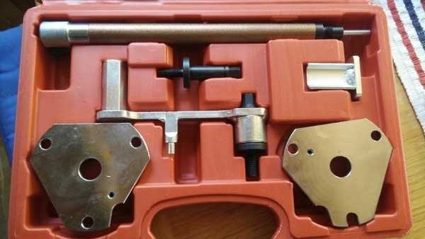
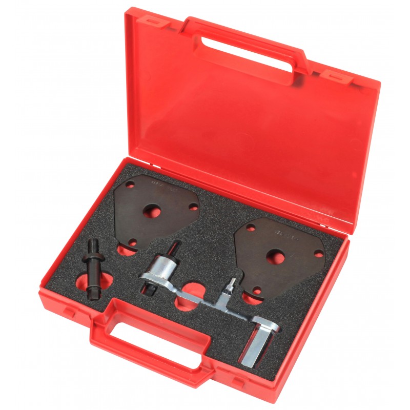
5) Most modern Fiat / OEM timing tool kits have both a crank TDC location setting tool/plate and valve/camshaft setting methods which take the errors out of setting both TDC and cam shaft positioning.
1) TDC will only be valid when BOTH the inlet AND exhaust valves are closed and the piston is on the up/compression stroke. You can not do it off just the cylinder height as whilst the piston may technically be at TDC the crank can be in any of four positions (four stroke engine)
2) On my old Tipo 1.6 Brio (K reg) I seem to recall that for some reason Fiat chose to do TDC off No.4 cylinder and not No.1
3) Doing TDC with a dial gauge is not very reliable if done off one cylinder only. This is because piston displacement is minuscule at TDC for crank angle. The best way to do it is with TWO dial guages to get No1 on the compression stroke up towards TDC and then rotate the crank backwards slowly. You are looking to get No1 & No4 piston or No.2 & No.3 pistons dead level. The smallest error in crank angle will make huge changes in piston levels. With this levelling set then the crank is exactly 90 degrees before TDC. Now you need a protector to dial up +90 degrees
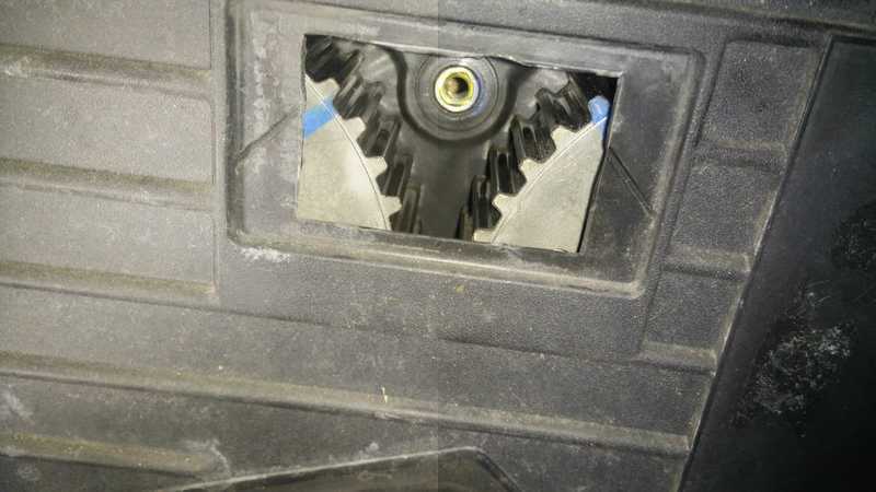
4) The cheats next most accurate method is to remove the battery, possible battery tray, or any other item that will allow you to get to the top of the bell housing. Here you will hopefully find a rectangular rubber bung (5cm by 3cm approx). Remove this bung to reveal an inspection / timing window. On the edge of the window casting you will find 3 notches. The left most (as viewed) is 0 deg./TDC, the middle is 5 deg. before TDC and the right most is 10 deg. before TDC. There may even be a 0 / 5 / 10 legend. If No.1 (or No4 if Fiat switched the reference point) is on the compression stoke at TDC then you will find a reciprocal drilled notch in the flywheel which you can accurately align with the 0 mark.
5) Most modern Fiat / OEM timing tool kits have both a crank TDC location setting tool/plate and valve/camshaft setting methods which take the errors out of setting both TDC and cam shaft positioning.
he takes a bit of paper, sticks it on the inlet cam-shaft lobe at no.2 cylinder to get the "shape" the lobe makes against the face of the head... then cuts out the shape so that the cut-out fits onto the cam-shaft lobe.
Ralf S.
Not quite what I did but you get the whole idea.
What I think he wants though is how to get the CAM kit without having a kit physically.
How do you do that ?
More detailed explanation.
I'll have to explain how I obtained this with illustrations. Cos I used a picture I found on Google and performed some little magic on it to get my paper cut out.
I'll try and do a video tomorrow (hopefully) and post the link here when I'm done.

Yes, I think if you spend a few quid on the timing tools and do the job yourself it pays for itself straight away.
Of course, no tools can work.. but it's like fixing your TV aerial by climbing on some boxes, rather than using a ladder. You only need to fall off once...
Ralf S.
Of course, no tools can work.. but it's like fixing your TV aerial by climbing on some boxes, rather than using a ladder. You only need to fall off once...
Ralf S.
Similar threads
- Replies
- 0
- Views
- 736