

I think I'm getting to the bottom of the problems with my high beams not working... I have fairly confidently narrowed it down to the BCM.
Briefly, the BCM gets a signal from the stalk/switch and is supposed to activate pin 9 which tells the headlamp relay to turn on the lights. I have a signal from the stalk (blue light comes on).. and activating the relay manually works the lights... so it looks like the BCM is not passing on the signal to the relay.
N.b. I have tried a different stalk and even an alternate (battery side) fuse box during my investigations. I'm 90% certain that the BCM is the main culprit.
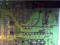
Now... I have removed the BCM and taken the lid off. On the PCB it looks like there are two tracks/circuits to the area around Pin 9.. (I can't quite see under there) and if you follow the tracks out, one of them has a small tarnished "break" (blackened/melted?) in it.
I have circled Pin 9 and "break". Does it look dodgy to anyone who knoes.... or is it normal? My mate Ollie who used to repair missiles for the navy says it looks like a repair..?
How can I test the circuit from the pin to the track just ahead of the "break", to see whether it is part of the Pin 9 circuit or just coincidentally close to it? If I can get a signal through pin 9 from just before the "break"... I'll be able to test what happens to the circuit on the other side of it.
Ralf S.
Briefly, the BCM gets a signal from the stalk/switch and is supposed to activate pin 9 which tells the headlamp relay to turn on the lights. I have a signal from the stalk (blue light comes on).. and activating the relay manually works the lights... so it looks like the BCM is not passing on the signal to the relay.
N.b. I have tried a different stalk and even an alternate (battery side) fuse box during my investigations. I'm 90% certain that the BCM is the main culprit.
Now... I have removed the BCM and taken the lid off. On the PCB it looks like there are two tracks/circuits to the area around Pin 9.. (I can't quite see under there) and if you follow the tracks out, one of them has a small tarnished "break" (blackened/melted?) in it.
I have circled Pin 9 and "break". Does it look dodgy to anyone who knoes.... or is it normal? My mate Ollie who used to repair missiles for the navy says it looks like a repair..?
How can I test the circuit from the pin to the track just ahead of the "break", to see whether it is part of the Pin 9 circuit or just coincidentally close to it? If I can get a signal through pin 9 from just before the "break"... I'll be able to test what happens to the circuit on the other side of it.
Ralf S.
")