Technical Changing Instrument Panel LEDs

Currently reading:
Technical Changing Instrument Panel LEDs

Joined
Mar 16, 2011
Messages
33
Points
7
changed and they took a picture of almost all the LEDs in may stiLo...
was now very different and far more beautiful.. ;)


usual place of indicators marking pen was opened, inserting the same mark to coincide loathed..​

litters molluscs should be removed by turning..
If the engine going down...​


solder and soldering iron with the help of LEDs would remove the original..​

then we want to make a soldering iron and solder again, LED color is in the making...​


led to the explosion of the computer screen is not transparent for the 2 layers of leaves, put the file..​


test time :)


gate arm control panel in the same way....​


but no longer as clear picture could not take full....​

 
Last edited:
do you have a link to where you got the LED's from? or what specification they are?

thanks

LED strip

143jip1.jpg


pr_01_474_max.jpg
 
theyd all be pretty std SMD devices i would have thought iirc the only difference in voltages would be dependant on what colour you wanted.

It is safe enough to assume 1.7 volts for non-high-brightness red, 1.9 volts for high-brightness, high-efficiency and low-current red, and 2 volts for orange and yellow, and 2.1 volts for green. Assume 3.4 volts for bright white, bright non-yellowish green, and most blue types. Assume 4.6 volts for 430 nM bright blue types such as Everbright.
(http://www.theledlight.com/LED101.html)
 
Last edited:
ok, i know that different colours require different voltages, but what PD does the LED footprint present? because surely that would determine what you can use.

example:
currently the stilo uses orange SMD LEDs, according to your list, @ ~V?. Aili has replaced them with white/blue SIMD LEDs, according to you list, @ ~3.V....where is this extra 1.4v going to come form? or is it literally just going to run dimmer?

also my understanding is that there are 3 different SIMD LED foot print sizes, each of which using a different voltage range. so the size of the LED used is important...especially before i buy a 100!
 
Last edited:
tbh id expect them to run a little dimmer but i dont think it would matter because youd be using larger MCD valued LEDs than std...

as for diamentions correct me if im wrong but i think they come in 0.6mm, 0.8mm and 1mm... if its 0.8mm as std then the solder you would be using would cover the +/- 0.2mm. id say a pretty safe bet that getting 0.8mm would suffice but i can see why your asking when buying in bulk!
 
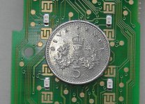
Once you've had some practice soldering your SMDs in, you could do some of these minute ones from the Connect Nav+ front panel. You'd need a pretty steady hand for them. :)
.
 

Attachments

  • SMD LEDs.jpg
    SMD LEDs.jpg
    126.3 KB · Views: 82
i have a trick up my sleeve :cool:

i work for a radio engineering company as an engineer...all day im repairing radios, de-soldering and soldeing minute things like that (uaully resistors and capacitors) but same principle....what makes the BIGGEST difference is the quality of soldeing iron, at work i use a weller solder station (EXCELLENT) at home i have a 40W homebase plugin cheapo (CRAP lol)

having said that, they are ****ing tiny! i thought that was a 10p!

id probably cheat, use solder paste and a hot air gun....
 
Once you've had some practice soldering your SMDs in, you could do some of these minute ones from the Connect Nav+ front panel. You'd need a pretty steady hand for them. :)
.

Davren,

I could get those repaired if you have some kicking about.
Can give them to the electronics guys at work.

let me know either here or pm me.

Cheers for now,
 
Wouldn't a hot air gun blow them off the board? or does the paste hold them in place long enough to solder them?

Some would use the paste to hold it, but it can get messy, i use a fine point.

The solder paste is literally just an aid. the aim of micro soldering is to make it so you only need two hands instead of three (as is normally the way lol).

the process as id do it as follows:
- Cut the old ones off, not worth de-soldering for fear of lifitng tracks (supprisingly easy), is commone practice to not re-use surface mount components.
- Heat up some solder wick on the pads to lift off the residue and old solder
- clean up with IPA
- apply a blob of solder paste on each pad
- drop the SMD on
- Hold down with a solder tool which is basically a point
- at the same time apply heat via hot air untill the solder paste turns to just solder
job done!

equal offer form me also Davren.
 
i can speak english good, i can tell all of the details :bang:
speak english told a beautiful details :bang:
No need to do extra processing.
Rip out the ones you put those LEDs indicators
Working with 12-volt
command of your television before trial experience to win (y)
 
Thanks for the offer guys but I only posted the picture to show how small these ones are.

I have two CN+ front panel PCBs here. All 38 LEDs work on each of them but on one of them 3 and the other 9 of the LEDs only work sometimes. On both PCBs, if I press on the same area while it's powered, all the LEDs work again. I've been searching for a cracked track or loose component but so far can't find anything. Took a high resolution photo of the area today and blew it up on screen but still can't find the fault.
 
sounds like a dry joint to me....dont laugh, but insted of "hunting" for it, try this:

- Buy some "no clean flux" from ebay or wherever
- Put bluetack and then foil over any capacitors (insulation)
- pre heat oven to 175 deg
- cover the boar din flux
- keep it flat and level and slightly raised (wooden blocks will do)
- put it in the oven, turn it up to 230 deg, once it gets there leave it for 4 mins at temp.
- then open oven door, let it cool before taking it out, then wil be safe to assume all dry joints are fixed....
 
Back
Top