General Rude Fiat Dealer

Currently reading:
General Rude Fiat Dealer

Evening guys
Take a photo of it is what I always do- i tend to take photos of everything these days with my memory:)

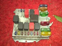
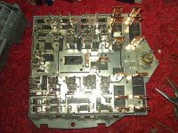
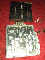
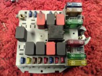
That's where T9 relay is so it's a good place to investigate. What so often happens is water gets in between the tracks on the circuit board, then this expands with corrosion and breaks it apart
 
As I remember, there is no circuit board in the fuse box, just seperate metal sockets, some of which were riveted together to form internal busbars.

Unlike my old Croma Turbo fuse box that had a 6 layer flexible PCB with several different layers riveted for common electrical contacts. That was a nightmare to dismantle and repair.
 
The car seems worse now than before, god knows what Fiat did to it. :(

Looks like the cables to the injector are almost cut through by some sort of tester probes. Can't remember if they were already done?(see attched photo)

I took the engine compartment fuse box out, stipped and cleaned it so it looked like new. I checked every fuse and relay before replacing them. I cleaned every connector again including D4. I then double check the relays by swopping them with the ones in my own car. Everything was 100% but the car still wont start.

The problem deffinately isn't anything to do with the engine compartment fuse box.
 

Attachments

  • 61.jpg
    61.jpg
    144.9 KB · Views: 118
  • 64.jpg
    64.jpg
    164.3 KB · Views: 111
  • 65.jpg
    65.jpg
    153.3 KB · Views: 77
  • 69.jpg
    69.jpg
    153.4 KB · Views: 119
  • 66.jpg
    66.jpg
    123.1 KB · Views: 66
Last edited:
My tip is faulty engine ECU. Sometimes works, sometimes not - looks like solder joint issue of main BGA processor.
 
At least that's something else ruled out.

I thought it was a JTD engine you were dealing with but your injector picture is for a petrol engine. I can't find anything in the thread to say what engine it is though?

Looks as though there are/were 3 wires going to the injector, I've only ever seen 2 for an injector?

Wires certainly look a bit butchered. Someone hasn't got an insulation piercing meter probe and has obviously been looking for a problem before.

I think ruling out individual components is the only way to solve this. Might be time consuming but we'll get there in the end, I hope.

Post 15
Engine - 1.6 16v

Yes, I'm unable to read any engine data at all. Died before I was able to connect the laptop. :(

Errors.
ASR
Security
Air Bag
Loose Connection(think this might be the problem)

Where's the main battery neg to engine earth connection on a 1.6?

Deffinately 3 wires at the injector. I think your right about the insulation piercing meter probes, possibley checking for power due to immo problem?

Wish I could find more about this error.

B1029 - Serial Line W

I can't find any info at all anywhere. :(
 
Last edited:
There's been a few posts about petrol engine ECU problems such as dry joints, cracked PCB tracks and poorly soldered connectors. None of the posts I can find say exactly where the problems were, just that people have re-soldered them.

My earlier post was the only thing I could find anywhere about B1029.

All I can find in eLEARN is that Serial Line W is for immobilizer recovery. Doesn't help much.
 
Thread's got too long to read it all again.

What's the actual problem now?

When it doesn't start, is the key/padlock symbol warning light illuminated?

Problems are the same as before except it wont start at all now:

ASR
Security
Air Bag
Loose Connection

is the key/padlock symbol warning light illuminated? Yes

I've just been looking through the elearn and noticed diagnostic port connector on the body computer has 6 Serial Lines. Might be a good place to start looking?

Edit
I think there are 3 different body computers, 3 door, 5 door and Multiwagon. Can you confirm?
 

Attachments

  • 2222.jpg
    2222.jpg
    125.4 KB · Views: 157
Last edited:
Connector M01G on the BC is the 16 pin diagnostic connector so that would have all the diagnostic serial K lines terminating there.

According to ePER there's 3 BCs for the MW, and one for some 3 door versions and several more suitable for both 3 and 5 door versions. A BC is ordered from Italy programmed to individual VINs so effectively, there's a specific one for every vehicle.

You've got eLEARN set for upto 06/2002. Is the car an early one? If so, does he have the 5 digit electronic security code? You could try the emergency start procedure which could confirm whether it's an immobiliser problem or not.

EDIT: I think pin 29 of connector A (Blue?) on the BC is serial line W. From the diagram, it's to the right of the diagnostic connector so could be a good starting point.
.
 

Attachments

  • BC Connectors.JPG
    BC Connectors.JPG
    39 KB · Views: 539
Last edited:
You've got eLEARN set for upto 06/2002. Is the car an early one? If so, does he have the 5 digit electronic security code? You could try the emergency start procedure which could confirm whether it's an immobiliser problem or not.

EDIT: I think pin 29 of connector A (Blue?) on the BC is serial line W. From the diagram, it's to the right of the diagnostic connector so could be a good starting point.
.

I've had the eLearn set for new and old looking for anything to do with Serial Lines. Regardless of year all the serial lines converge at the body computer due to the diag socket. Car is 2004.

"pin 29 of connector A (Blue?)" (y)
Item 4 in the diagram, "IN/OUT recovery serial for NCM in case of break in C-CAN line". Its the only IN/OUT serial line I've seen so may be your right, this one is Serial Line W and the rest are Serial Line K.

I'll check that for continuity tomorrow.
 
Last edited:
Shadeyman: I think, that focus on security failure is the right decision.
There is a procedure in car manual, to set security code in engine ECU without working CAN-line. In properly working car, body computer send code to engine ECU and key/padlock light goes off. When there is a problem on CAN-line, no code send. But with this procedure you can set the code manualy - it is about counting blinking key/padlock light and pressing gas pedal. I think you should try it.
 
If you need to go tackling inside the ECU then here's some helpful pics I took of my 1.6 engine ECU
1.6 ecu cb 2.JPG
There's a 4mm deep groove of sealant all the way around holding the cover on which you'd need to cut around with a sharp knife (see blue arrow) and one leverage point (green arrow) as a start point to carefully lever the thin metal cover up and away

Inside, the two ECU connector pin sets (circled in red) are hotballed in at manufacture (whole CB area heated up to solder). Then of course the ECU is mounted on top of a hot engine which is not that smart a place as the thing is slowly cooking its whole life long

I simply redid the ecu connector pin solder joints by placing a hot iron on each connector pin joint for around 4 secs, when you see the solder move, that's it. Make sure all the pins are level at the same height on the other side. A good light and a magnifying glass is recommended:)
 
Last edited:
Deckchair5: Maybe there is problem in pins of connector, but more possibly the problem is in main ECU procesor in BGA socket. This procesor is on opposite side and you need unsolder these connectro pins to get the PCB out. Like this:

IAW5_NF_T1_proc.jpg


And processor and eeprom in detail:
IAW5_NF_T1_detail.jpg


Socket BGA means thehe is not classic pins, but "tin balls" to connect processor to the PCB. It is usual that there can be cracks.
See "bga reballing" on youtube or google.
Sorry my poor english.
 
Shadeyman: I think, that focus on security failure is the right decision.
There is a procedure in car manual, to set security code in engine ECU without working CAN-line. In properly working car, body computer send code to engine ECU and key/padlock light goes off. When there is a problem on CAN-line, no code send. But with this procedure you can set the code manualy - it is about counting blinking key/padlock light and pressing gas pedal. I think you should try it.

Could you give me a step by step procedure to set security code in engine ECU and I'll give it a try, sounds like a good idea.
 
Car is 2004.

I believe the emergency start procedure was abandoned on later cars. The procedure is described in my 2003 handbook but it's not in the 2006 one so it may work on a 2004 model if he has or wants to get the 5 digit code.

If the car started with the code, it would confirm that the problem was the immobiliser so you could ignore everything else.

"pin 29 of connector A (Blue?)" (y)
Item 4 in the diagram, "IN/OUT recovery serial for NCM in case of break in C-CAN line". Its the only IN/OUT serial line I've seen so may be your right, this one is Serial Line W and the rest are Serial Line K.

I'll check that for continuity tomorrow.

I think there may be a labelling mistake on the wiring diagram below (pin A29 is labelled as B29 which according to the connectors list you posted yesterday is for hazard warning), but it looks as though pin A29 of the BC goes to pin A11 of the 1.6 engine management ECU (M10) and should be a Grey/White (HB) wire.
 

Attachments

  • CODE Wiring.JPG
    CODE Wiring.JPG
    99.1 KB · Views: 490
Back
Top