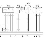
Hey all, am after a wiring diagram for the fiat stilo 1.4 16v ( same as 1.2 16v) Absolute pressure/temp sensor thats in the manifold.
According to elearn the 'integrated air temp sensor'
Pin 1 = L.blue red to ECU Pin 26
Pin 2 = grey red to ECU Pin 55
Pin 3 = grey to ECU Pin 7
Pin 4 = white to ECU Pin 6
The wire colours match the loom i have
Im basically trying to connect this sensor to a 1.2 16v punto sporting loom which the colours i have are:
Pin A = Black
Pin B = L.Blue Black
Pin C = Pink Black
Pin D = L.Blue Yellow
I can also not work these out.
Would love to just fit the punto sensor into the manifold, but its too long.
Anybody have any hints or tips. :worship:
Dan


