

You are using an out of date browser. It may not display this or other websites correctly.
You should upgrade or use an alternative browser.
You should upgrade or use an alternative browser.
Technical Instrument cluster wiring.
- Thread starter bfbenf
- Start date
Currently reading:
Technical Instrument cluster wiring.


- Joined
- Jan 20, 2013
- Messages
- 6,151
- Points
- 1,228
what pin
Italian Job
Member
- Joined
- Jan 20, 2013
- Messages
- 6,151
- Points
- 1,228
does this help
was this filmed with potato?
- Joined
- Jan 20, 2013
- Messages
- 6,151
- Points
- 1,228
I didn't need the instrument cluster so I wondered what pin was the fuel level?
cant find anything in autodata
Italian Job
Member
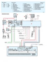
Accordng to the documents i have the fuel level is sent to the Body Computer the via canbus to the cluster (See below) Pins 4 and 15
Body computer functions include:
Receiving control signals from switches
Activating indicators, courtesy lamps, etc.
Acquiring, converting and transmitting signals to the CAN-bus (ABS, fuel level, etc.)
Managing fault diagnosis of the connectors involved and transmitting to the CAN-bus
Control of exterior lighting via semiconductors or relays
Function checks - faults signalled to instrument panel via CAN-bus
Body Computer connector A
1 Left hand door open switch
2 Left side indicator repeater lamp
3 Right rear indicator lamp
4 Fuel level sensor (+)
5 Left tail lamp
6 Right tail lamp
7 Alarm sensor serial line
8 Left front door lock - open signal
9 Not connected
10 Autoclose serial line (may be for electric windows)
11 Right hand door open switch
12 Left rear indicator lamp
13 Right side indicator repeater lamp
14 Handbrake "on" switch
15 Fuel level sensor (-)
16 Left rear door lock - open signal
17 Right front door lock - release signal
18 K-line aggregate 3
19 Not connected
20 Not connected
21 Courtesy lamp timer control
22 Right hand brake lamp
23 Courtesy lamp supply
24 Left front door lock - release signal
25 Right front door lock - open signal
26 Left rear door lock - open signal
27 Alarm sensor supply
28 Not connected
29 Not connected
30 Not connected
31 Left rear fog lamp
32 Left hand brake lamp
33 Boot lamp supply
34 Left front door lock - locking signal
35 Right front door lock - locking signal
36 Boot open switch
37 Not connected
38 Not connected
39 Not connected
40 Not connected
Italian Job
Member
I think it should be but not 100% certain. Using a multimeter you should be able to work out where pin 4 and 15 is. Pin 1 should be top left or right.
stevehebburn
New member
hi,i have a panda mj 2005.") does anyone know which 2 of the 13 cables( on instrument cluster multiplug) connects/ supplies signal, to power steering failure light symbol ? and also oil warning light ? thank you. cheers. steve
does anyone know which 2 of the 13 cables( on instrument cluster multiplug) connects/ supplies signal, to power steering failure light symbol ? and also oil warning light ? thank you. cheers. steve
does anyone know which 2 of the 13 cables( on instrument cluster multiplug) connects/ supplies signal, to power steering failure light symbol ? and also oil warning light ? thank you. cheers. steve
Last edited:
stevehebburn
New member
hi, yes, i know i posted in punto section. sorry can anyone help with my panda instrument panel problem . looks same as punto. cheers, steve.
can anyone help with my panda instrument panel problem . looks same as punto. cheers, steve.Similar threads
- Replies
- 1
- Views
- 544