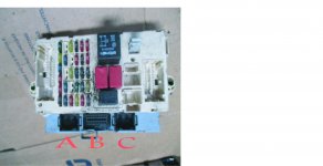
Body Computer connector A
1 Left hand door open switch
2 Left side indicator repeater lamp
3 Right rear indicator lamp
4 Fuel level sensor (+)
5 Left tail lamp
6 Right tail lamp
7 Alarm sensor serial line
8 Left front door lock - open signal
9 Not connected
10 Autoclose serial line (may be for electric windows)
11 Right hand door open switch
12 Left rear indicator lamp
13 Right side indicator repeater lamp
14 Handbrake "on" switch
15 Fuel level sensor (-)
16 Left rear door lock - open signal
17 Right front door lock - release signal
18 K-line aggregate 3
19 Not connected
20 Not connected
21 Courtesy lamp timer control
22 Right hand brake lamp
23 Courtesy lamp supply
24 Left front door lock - release signal
25 Right front door lock - open signal
26 Left rear door lock - open signal
27 Alarm sensor supply
28 Not connected
29 Not connected
30 Not connected
31 Left rear fog lamp
32 Left hand brake lamp
33 Boot lamp supply
34 Left front door lock - locking signal
35 Right front door lock - locking signal
36 Boot open switch
37 Not connected
38 Not connected
39 Not connected
40 Not connected
Body Computer connector B (EOBD socket)
1 K-line ABS control unit
2 Not connected (standardUS)
3 K-line Air bag control unit
4 Power earth
5 Signal earth
6 CAN-bus B
7 K-line engine ECU, auto-transmission
8 K-line immobilizer
9 Preparation for aggregates 1 (dashboard)
10 Not connected (standardUS)
11 Anti-theft device (alarm)
12 Preparation for aggregates 2 (front)
13 Preparation for aggregates 3 (rear)
14 CAN-bus A
15 Not connected (L-line)
16 Supply
Body Computer connector C
1 Reversing signal for steering column switch
2 Not connected
3 Screen
4 Immobiliser CODE aerial
5 Immobiliser CODE aerial
6 ABS serial line
7 Speedometer signal from ABS
8 Front fog lamps relay R14
9 Main beam relay R2
10 INT supply for speedometer generator
11 Not connected
12 Not connected
13 Headlamp washer switch on column
14 Headlamp washer relay R17
15 Earth for speedometer generator
16 K-line for ABS
17 Speedometer signal from pulse generator
18 Brake fluid level sensor
19 Alternator +D signal
20 K-line for ECU diagnostics
21 RF aerial earth (another source states pin C3)
22 Not connected
23 Not connected
24 Bonnet open switch
25 Alarm siren serial line
26 CAN-bus A for electric steering
27 CAN-bus B for electric steering
28 Repeater for speedometer signal
29 ISO5 interface - immobiliser and ECU
30 Right front sidelight
31 RF aerial (another source states pin C1)
32 Not connected
33 Not connected
34 Alarm supply (alarm siren)
35 Preparation for aggregates 2 (K-line for diagnosis)
36 CAN-bus A from ECU
37 CAN-bus B from ECU
38 Left front indicator
39 Right front indicator
40 Left front sidelight
Body Computer connector D
3 Instrument supply (+30)
4 Dipped beam switch on column
5 CAN-bus A to instrument panel
6 CAN-bus B to instrument panel
7 Indicator switch on column (left or right?)
8 Earth, passenger dashboard
9 Earth, passenger dashboard
Body Computer connector E
12 K-line for air bag control unit
20 Front fog lamps switch
22 Radio
Body Computer connector F
29 Hazard switch lamp
30 Indicator switch on column (left or right?)
31 Instrument supply (+15)
32 Heated rear window switch
33 Main beam switch on column
34 Hazard lamps switch
35 Rear fog lamp switch
36 Instrument supply (-)
NOTE: Pin numbering suggests D, E and F share a 36 way plug/socket
Body Computer connector Y (connects directly pin for pin to plug X on passenger fusebox)
1 Central locking supply
2 Top brake lamp signal (ponit between switch and lamp)
3 Reversing signal (point between switch and lamp)
4 Not connected
5 CAN-bus B to fusebox connectors E5 (radio) and D28
6 Heated rear window relay R11
7 CAN-bus A to fusebox connectors E17 (radio) and D10
8 Dipped headlamp relay R1
9 INT supply for body computer (ignition on, before F37)
10 Door locking motors
11 Door unlocking motors
12 Light system supply from ignition switch
13 INT supply for Instrument panel connector (ignition on after F37)
14 Sunroof, electric windows relay R13
15 Heater controls and cigar lighter illumination and number plate lamps
16 Not connected
17 Services / SMBT services supply
18 Body computer supply (immob., CAN-bus, sidelight, rear fog lamp)
19 Supply for indicators, hazards, instrument panel connector (via F53)
20 Central locking earth


