Technical DET3 ecu wiring?

Currently reading:
Technical DET3 ecu wiring?

dac69er

Established member
Joined
Nov 26, 2014
Messages
1,122
Points
333
Location
suffolk
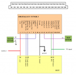
can someone confirm the wiring of a DET3 as per this modified diagram from the ecumaster website.
their original wiring shows the 12v, ground and TPS connections just being wired direct to each other between the ECU and the DET3, i cant see that working???

i assume you only have to cut and intercept the MAP and CRANK sensor? the TPS, ground and 12v are commoned up to both the DET3 and the ECU?


thanks
 

Attachments

  • Capture.PNG
    Capture.PNG
    81.9 KB · Views: 1,338
You intercept the crank sensor as it's modifying the signal so that's in series with DET3.

Everything else You common up as IAW needs all sensors to generate timing corrections and do idle while DET3 does fuelling and timing mod while using the same TPS and coolant sensors.

MAP sensor 32 in this scheme refers to an outboard MAP sensor with bigger resolution for forced induction - it's confusing since latest iterations of DET3 have inboard MAP.

If connecting to use for Fuel Implant mode - injectors go directly from DET3 and we used a common + from stock wiring harness.

If connecting to full piggyback You probably common up the fuel as well.

thanks for the reply.

i am still a little confused about the crank sensor wiring?
you cut the wire from the sensor, join to terminal 9 on the det 3, then from terminal 5 to terminal 28 on the ecu?


it then shows you connect terminal 4 on the det 3 to terminal 11 on the ecu and ground the wire that used to go to terminal 11 on the ecu?


i also assume that if you say the newer det3 has an inbuilt map sensor that you dont have to link the original one in, that can just wire directly to the ecu as normal?

its an awful drawing. i am an electrical engineer and it just isnt making much sense! it should be so simple :bang:
 
Crank sensor goes into the DET3 and then from DET3 to the stock ECU.

Think of the DET3 as the crank sensor as it is in this instance a fake crank sensor.
 
Crank sensor goes into the DET3 and then from DET3 to the stock ECU.

Think of the DET3 as the crank sensor as it is in this instance a fake crank sensor.

i get that bit.

what i dont really get is that the crank sensor is 3 wire, but it is only showing 2 wires on the diagram?

you wire 1 wire into the det3 and then 2 wires come out. i am just trying to understand the logic of the drawing as it just seems a little inconsistent.

i wanted to ensure i was understanding it correctly.
 
Back
Top