Matt,
1. You have not stated whether you query relates to a basic heater or aircon, but on the x250 the heater fan wiring seems similar.
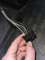
2. Both diagrams for the x250 show a resistor pack connector with 5 ways. Pin 4 (your red wire) is not used so for the moment tape it up safely. It seems that you have a non OEM connector, and it may have other applications.
3. Please confirm your statement that applying 12V to either the black or red wire makes the fan run at full speed. Do you mean connecting to chassis/earth instead? (As I think you will appreciate, the fan motor is supplied via an ignition controlled relay and a large fuse, (40A?) in the engine bay fusebox. Applying a 12V +ve to both sides of the motor will not make it work.)
4. The heater motor uses a chassis connection close to the motor. It is worth checking that this is not loose or otherwise faulty.
5. For testing a 12V test lamp is useful, as it can prove a circuit through the motor etc., while a modern multimeter can be misleading due to its high sensitivity giving a reading through a faulty connection.
6. With the test lamp connected to chassis, check that it illuminates when connected to your black or red wires, with ignition ON.
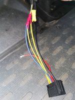
7. If OK try at pin 1 of your resistor pack. This will prove continuity of the new resistor pack. If OK, the next logical step would be to check at the speed switch, where I read pin 2 for speed 1, as connecting to the white wire in your picture. Pin 1 at the switch is the chassis connection.
I appreciate that there is an access problem here. Someone else may have a better idea.
When you get to the point where your test lamp does not illuminate, you have worked past the fault. It should not illuminate at pin 1 of the switch, bit at all other pins with ignition ON. If aircon fitted leave it OFF while testing.
I hope that this helps.