Technical Wiring diagram for gearbox sensor 1.9 Multijet

Currently reading:
Technical Wiring diagram for gearbox sensor 1.9 Multijet

Joined
Oct 13, 2007
Messages
172
Points
85
Location
London
The gearbox speed sensor wiring on my 2006 Doblo 1.9 multijet has been connected via a connector block and it doesn't seem to be wired up in the correct sequence.
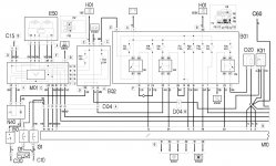
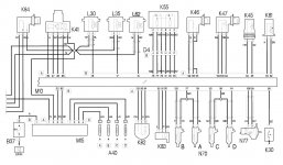
Has anyone out there got a wiring diagram for this section.
Would be great to get my van out of limp mode!!!
 
Below is the only speed sensor wiring diagram I have for the Doblo. Not sure which years it covers.

E50 = Speedometer
K84 = Speedometer Sensor
M01 = Body Computer

Wiring Colour Codes:
NZ = Black/violet
VN = Green/black
L = Blue
.
 

Attachments

  • Doblo 1.JPG
    Doblo 1.JPG
    157.9 KB · Views: 304
  • Doblo 2.JPG
    Doblo 2.JPG
    143.7 KB · Views: 300
M15 = Glowplug Control Unit.
A40 = Glowplugs

The glowplugs (A40) are powered from the control unit (M15) dependant on signals sent from the engine management ECU (M10).
.

I've got 1.5v at terminal 3 of K84 and 4.6v at terminal 2 of K84 too.
I think that 1.5v is too low and I believe it should be around 8 Volts.
I have a glow plug fault on my dash that flashes about 10 times, every time I start the van. I've recently changed the glow plug module, but no change.
I removed the engine a few months back and think I might have damaged wire no.2 coming out of the glowplug control unit.
I see that wire no.2 of the glowplug control goes to a point and then splits off to power 7 items in total inc. K84 speed sensor.
I'll try to find the point where all the wires meet or run a wire from terminal 2 of the gp relay straight to no.3 of K84 and hope that it works.
If that doesn't work I'll have to look at the voltage coming out of the ecu via wires no.22+62 to the gp relay no. 2 +5.
 
Any idea what DO4 A is?
I had the van plugged in today and it looks like theres a broken wire somewhere between the speedo drive and the ecu.
 
Back
Top